Cub Crafters XCub 60cc Instruction Manual Bedienungsanleitung Manuel d’utilisation Manuale di Istruzioni
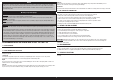
SPECIFICATIONS • SPEZIFIKATIONEN • SPÉCIFICATIONS • SPECIFICHE 116.0 in (294 cm) 1908 sq in (123.1 dm2) Total 82 in (208 cm) 27–31 lbs (12.0–14.
Part # English Deutsch Français REQUIRED RADIO EQUIPMENT • ERFORDERLICHE RC AUSRÜSTUNG • ÉQUIPEMENT RADIO REQUIS • APPARECCHIATURE RADIO NECESSARIE DUB671 Super Strength Long Servo Arm: JR Hochfester langer Servoarm: JR Long bras de servo robuste : JR EFLRYH9TR Triple Plug Y Harness Y-Kabelbaum mit Dreifach-Stecker Harnais en Y à triple prise SPMA3005 Heavy-Duty Servo Extension 24-inch Servokabelverlängerung 600 mm (24 inch) Rallonge de servo, 600 mm SPMA3006 Heavy-Duty Servo Extension 36-inch Servokabelv
Part # English Deutsch REQUIRED TOOLS • BENÖTIGTES WERKZEUG • OUTILS REQUIS • ATTREZZI NECESSARI Box wrench: 12mm, 1/2-inch Ringschlüssel: 12mm, 1/2-inch Drill Bohrer Drill bits: 5/64-inch, 3/32-inch, 7/64-inch, Bohrer: 1,5 mm, 2mm, 2,5mm, 3mm, 3,5mm, 5mm 1/8-inch, 9/64-inch, 3/16-inch Epoxy brush Pinsel Felt-tipped pen Faserstift Flat blade screwdriver, small and large Schraubendreher flach Flat file Flachfeile Hemostats Klemme Hex wrench: 1.5mm, 2mm, 2.5mm, 3mm, Inbusschlüssel: 1,5mm, 2mm, 2.
OPTIONAL SCALE ACCESSORIES We have worked with various vendors to develop scale details specifically for this model. These items include pilot figures, decals, propellers, wheels and shocks. Pilots: www.tailoredpilots.com www.warbirdpilots.com OPTIONALES MASSSTABSGETREUES ZUBEHÖR Wir haben mit verschiedenen Anbietern zusammengearbeitet, um maßstabsgetreue Einzelteile speziell für dieses Modell zu entwickeln. Zu diesen Einzelteilen zählen Pilotenfiguren, Decals, Propeller, Räder und Stoßdämpfer.
Batteries Always follow the manufacturer’s instructions when using and disposing of any batteries. Mishandling of Li-Po batteries can result in fire causing serious injury and damage. Small Parts This kit includes small parts and should not be left unattended near children as choking and serious injury could result. NOTICE All instructions, warranties and other collateral documents are subject to change at the sole discretion of Horizon Hobby, LLC. For up-to-date product literature, visit horizonhobby.
Propeller Halten Sie lose Gegenstände die sich im Propeller verfangen können weg vom Propeller. Dieses gilt auch für Kleidung oder andere Objekte wie zum Beispiel Stifte oder Schraubendreher. Halten Sie ihre Hände weg vom Propeller, es besteht akute Verletzungsgefahr. Akkus Folgen Sie immer den Herstelleranweisungen bei dem Gebrauch oder Entsorgung von Akkus. Falsche Behandlung von LiPo Akkus kann zu Feuer mit Körperverletzungen und Sachbeschädigung führen.
L’hélice Gardez éloignés tous les éléments qui pourraient être attrapés par l’hélice. Cela inclut les vêtements larges ou les objets comme des outils par exemple. Gardez toujours vos mains à distance pour éviter tout cas de blessures. Les batteries Suivez toujours les instructions du fabricant de vos batteries. Une mauvaise manipulation d’une batterie Li-Po peut entraîner un incendie causant de graves dégâts matériels et des blessures corporelles.
Elica Tenere gli oggetti liberi (vestiti, penne, cacciaviti, ecc.) lontano dall’elica, prima che vi restino impigliati. Bisogna fare attenzione anche con le mani perché c’è il rischio di ferirsi anche gravemente. Batterie Quando si maneggiano o si utilizzano le batterie, bisogna attenersi alle istruzioni del costruttore; il rischio è di procurare incendi, specialmente con le batterie LiPo, con danni e ferite serie.
REMOVING WRINKLES ENTFERNEN VON FALTEN ÉLIMINATION DES PLIS TOGLIERE LE GRINZE The covering of your model may develop wrinkles during shipping and will require the use of a heat gun (HAN100) and covering glove (HAN150) or covering iron (HAN101) with a sealing iron sock (HAN141) to remove them. Use caution while working around areas where the colors overlap to prevent separating the colors. Avoid using too much heat, which could separate the colors.
CONTROL HORN INSTALLATION 1. Insert the M3 x 15 socket head cap screw into the hole in the aileron control horn. Remove any paint using a hobby knife and #11 blade so the screw fits into the hole easily. Check all the control horns. 2. Use medium-grit sandpaper to lightly sand the aileron control horn where it fits into the aileron. Clean the sanded area using a paper towel and isopropyl alcohol to remove any debris or oils. This provides the surface texture necessary for the epoxy to bond to. 6.
AILERON SERVO INSTALLATION 11. Use a felt-tipped pen to mark the control horn on both sides of the rudder. This will indicate the area of the control horn where the paint must be removed. 16. Remove the aileron servo cover from the wing. Tape the string to the wing so it won’t fall into the wing. 12. Remove the control horn from the rudder. Place tape against the lines drawn to prevent removing any unwanted paint. Use medium-grit sandpaper to lightly sand the control horn where it fits into the udder.
21. Fit the servo between the servo mounting tabs in the aileron servo tray. The servo arm will be centered in the slot. Mark the locations for the servo mounting screws using a pencil, then remove the servo. 26. Use the string to pull the servo lead through the wing and out at the root. 22. Use a drill and a 5/64-inch (2mm) drill bit to drill the holes for the servo mounting screws in the locations marked in the previous step. 27. Secure the servo to the wing using four M2.5 x 10 selftapping screws.
FLAP SERVO INSTALLATION 36. When attaching the linkage to the servo arm, use the hole in the arm that is 5/8-inch (16mm) from the center of the arm. Enlarge this hole using a pin vise and 1/8-inch (3mm) drill bit. 31. Center the servos and install the servo arms on the servos perpendicular to the servo centerline. Prepare both the right and left flap servos. 5/8 inch (16mm) 32. Remove the flap servo cover from the wing.
41. Check the operation of the flap using the radio system. Trim the sheeting using a hobby knife and #11 blade if any of the hardware contacts the sheeting. 46. Use hobby scissors or a hobby knife with a new #11 blade to trim the flap linkage cover. Use care not to chip or damage the paint. 42. Secure the servo to the wing using four M2.5 x 10 selftapping screws. Use a #2 Phillips screwdriver to tighten the screws. 47.
51. Place the nylon bushing in position in the center of the cover. 56. Secure the axle bolt to the landing gear using the axle bolt lock nut. Use a 6mm hex wrench and 1/2-inch nut driver to tighten the hardware. Once tightened, make sure the wheel can spin freely on the axle bolt. Use a 1/2-inch open end wrench if necessary to hold the inner nut in position when tightening the hardware. 52. Fit the remaining aluminum wheel hub into position, aligning it with the notches in the tire.
61. Once the CA has fully cured, attach the landing gear cover to the fuselage using two M2.5 x 10 sheet metal screws and a #2 Phillips screwdriver. 66. Attach the cross brace to the inner holes on the landing gear mounts using two M3 x 15 socket head cap screws and two M3 lock nuts. Tighten the hardware using a 2.5mm hex wrench and 5.5mm nut driver. 62. The remaining two screws can be installed, completing the installation of the landing gear covers.
71. Slide the axle into the main landing gear. Place a drop of threadlock on the two M3 x 3 setscrews. Thread the setscrews into the gear, tightening them on the flat areas of the axle. Use a 2mm hex wrench to tighten the setscrews. 75. Attach the strut fitting near the aileron to the bottom of the wing using two M3 x 15 socket head cap screws. Apply a drop of threadlock on each screw before tightening them using a 2.5mm hex wrench. Use care not to overtighten the setscrews and damage the threads.
80. Thread the strut end fitting on the threaded rod at the end of the strut. Adjust the position of the end so there is no stress on the strut when it is attached to the fitting. Attach the fitting to the mount using an M3 x 15 socket head cap screw, two M3 washers and an M3 locknut. Tighten the hardware using a 2.5mm hex wrench and 5.5mm nut driver. 81. Slide the outer strut fairing against the wing. Mark the locations for the three mounting screws on the wing. 85.
89. Cut two pieces of card stock that are 1/2 x 2 inches (13 x 25mm). Make a 1/8-inch (3mm) hole in each piece. Tape the card stock to the fuselage with the hole aligned with the blind nut in the fuselage. 94. Fit the fairing back on the strut. Attach the struts to the fuselage, then attach the fairing to the fuselage using two M3 x 15 socket head cap screws and two M3 washers. Tighten the screws using a 2.5mm hex wrench. Place a drop of canopy glue on the screws before installation.
99. Measure from each wing tip to each stabilizer tip. Adjust the stabilizer so the measurements are the same for both sides. 104. Slide the stabilizer through the fuselage and apply epoxy to the exposed wood on the top and bottom of the stabilizer. A A A=A 100. Use a felt-tipped pen to transfer the fuselage outline onto the top and bottom of the stabilizer. 105. Slide the stabilizer into position. Remove any epoxy from the fuselage and stabilizer using a paper towel and isopropyl alcohol.
109. Use a ruler and carefully cut the covering 1/8 inch (3mm) below the line drawn on the fin to remove the covering. Remove the covering from both sides of the fin. Use care not to cut into the underlying wood, weakening the fin. 114. Fit the fin back into position. Continually check the alignment of the fin to the stabilizer as the epoxy cures. HINGING THE ELEVATORS AND RUDDER Use a covering iron to seal the covering to the underlying structure before trimming the covering.
119. Slide the hinge into position. Position the hinge so it is perpendicular to the hinge line when fully deflected. 124. Use a small amount of epoxy of contact adhesive to glue the position light in the rudder. 120. Insert the hinge so the center of the hinge point aligns with the front edge of the bevel on the control surface. Check that the hinge can move freely. Use a paper towel and isopropyl alcohol to remove any excess epoxy. Allow the epoxy to fully cure for all hinges before proceeding. 125.
RUDDER PULL-PULL CABLE INSTALLATION 129. Install the receiver in the fuselage. Mount any remote receivers in the fuselage using hook and loop tape. Follow the instructions included with the receiver for the correct locations for the remote receivers. 134. Thread a ball end eight turns on each of the four cable fittings. Apply a small amount of 5-minute epoxy to the hook and loop tape to secure it to the radio tray. 130. Remove the covering from the fuselage side using a hobby knife and #11 blade.
Install both sides of the cable at the same time. This will result in equal tension on both cables. 139. Retrieve the cable inside the fuselage near the rudder servo. 144. Slide a sleeve on the cable, slide the cable through the fitting, then back through the sleeve. Lightly tension the cables, then use crimping pliers to secure the sleeve to the cables. Use side cutters to remove any excess cable. The rudder cables may stretch slightly over time.
148. Slide the elevator pushrod into the pushrod tube. Use the radio system to center the elevator servo. Install the servo arm so it is 90 degrees to the pushrod. 153. Secure the wheel using the M4 locknut. Use a 3mm hex wrench and 7mm nut driver to tighten the hardware. Make sure not to over-tighten the hardware, preventing the wheel from rotating. 149. Thread the ball end on the elevator pushrod. Adjust the ball end so the elevator is centered when the elevator servo is centered.
158. Place a drop of threadlock on each of the tail wheel leaf spring mounting screws. Secure the tail gear to the fuselage using the screws and a 2.5mm hex wrench. 163. Thread an M3 nut on the cable fittings, place a silicone retainer on the clevis, then thread the clevis on the fitting so the end of the fitting is barely visible between the forks of the clevis. Prepare all four fittings. 159. Use pliers to bend the spring ends so the overall length is 3 inches (76mm) Prepare both springs. 164.
168. Once all the cables have been installed, check the tension on the cables. There should be light tension on the cables. Slide the retainer over the forks of the clevis. 172. Attach the motor box to the fuselage using four M5 x 20 socket head cap screws and four M5 washers. Place a drop of threadlock on each screw before their installation. Tighten the screws using a 4mm hex wrench. 169. Apply a drop of threadlock near the clevis, then thread the nut over the threadlock and against the clevis.
GAS ENGINE INSTALLATION 182. Attach the engine to the engine mount using four M6 x 100 socket head cap screws, four M6 flanged nuts and the four aluminum standoffs. Apply a drop of threadlock to the end of each screw before threading the nut onto the screw. Tighten the hardware using a 5mm hex wrench and 10mm nut driver. 177. Prepare the stopper assembly by placing small amounts of solder on the end of the tubes shown. This will help keep the fuel lines secure when installed.
Motor installation other than the Evolution® 62GX: The measurement from the firewall to the drive washer should measure 71/2 inches (190.5mm). Make any necessary adjustments to achieve this measurement. 191. Attach the clevis to the throttle servo arm following the instructions provided with the engine. Check the operation of the throttle using the radio system. Make any adjustments necessary so the carburetor opens and closes fully without binding the servo.
194. Place the radio hatch cover in position on the bottom of the fuselage. Secure the cover using two M3 x 15 socket head cap screws and two M3 washers. Use a 2.5mm hex wrench to tighten the screws. 199. Remove the seat and secure the cockpit floor in the fuselage using the screws previously removed. Place a drop of canopy glue on the screws before installation. This will keep the screw from vibrating loose yet leave them easily removable if necessary. SEAT INSTALLATION 200.
COWLING INSTALLATION 204. Tape the front window in position. Mark the window at the division between the top hatch and fuselage. 209. Cut four pieces of card stock that are 1/2 x 2 inches (13 x 51mm). Make a 1/8-inch (3mm) hole in each piece. Tape the card stock to the fuselage with the hole aligned with the blind nut in the fuselage. 205. Use a hobby knife with a new #11 blade to cut the windshield. The rear flat area will be glued to the canopy hatch. 210.
214. Fit the cowling to the fuselage. Trim the cowling as necessary to fit around the muffler. Secure the cowling to the fuselage using four M3 x 15 socket head cap screws and four M3 washers. Tighten the screws using a 2.5mm hex wrench. 217. Position the propeller so it does not contact the spinner cone. It may be necessary to trim the spinner cone to clear the propeller depending on the choice of propellers. Place a drop of canopy glue on the screws before installation.
TOW HOOK INSTALLATION (OPTIONAL) 227. Center the tow release servo and place the servo arm on the servo perpendicular to the servo centerline. 222. Remove the covering from the fuselage for the tow hook release using a hobby knife and #11 blade. Mount the tow hook release in the top of the fuselage. Make sure the slot in the release is parallel to the trailing edge of the wing. Use a drop of threadlock on the nut to prevent it from vibrating loose. 223.
232. Secure the servo arm using the screw provided with the servo. DECAL INSTALLATION 233. Apply the decals to your model using the box art from your model as a guide to location. Use a spray bottle and a drop of dish washing liquid or glass cleaner sprayed in the location of the decal to allow repositioning of the decal. Use a paper towel as a squeegee to remove excess water from under the decal. Allow the model to rest overnight so the remaining water can evaporate.
CENTER OF GRAVITY CONTROL THROWS An important part of preparing the aircraft for flight is properly balancing the model. The Center of Gravity range supplied here is a guideline based on testing. Deviation from the measurements we provide is possible and may result in a model that suits your flying style better. Start with the recommended Center of Gravity, then feel free to experiment with different balance points. We advise adjusting progressively and cautiously. 1.
PREFLIGHT CHECKLIST DAILY FLIGHT CHECKS LIMITED WARRANTY • Charge the transmitter, receiver and motor battery for your airplane. Use the recommended charger supplied with your radio system. Follow the instructions provided with the radio. Charge the radio system the night before each flying session. Charge the transmitter and receiver batteries using only included or manufacturer-recommended chargers. Follow all manufacturer’s instructions for your electronic components.
Inspection or Services If this Product needs to be inspected or serviced and is compliant in the country you live and use the Product in, please use the Horizon Online Service Request submission process found on our website or call Horizon to obtain a Return Merchandise Authorization (RMA) number. Pack the Product securely using a shipping carton. Please note that original boxes may be included, but are not designed to withstand the rigors of shipping without additional protection.
MONTAGE DES STEUERHORNS 1. Die M3 x 15 Zylinderkopfschraube in das Loch auf dem Steuerhorn des Querruders einführen. Farbe mit einem Hobbymesser und einer Nr. 11-Klinge entfernen, damit die Schraube problemlos in das Loch passt. Alle Steuerhörner überprüfen. 2. Mit Sandpapier mittlerer Körnung das Querruder-Steuerhorn dort leicht schleifen, wo es in die Klappe eingesetzt wird. Den mit Sandpapier bearbeiteten Bereich mit einem Papiertuch und Isopropylalkohol von Schmutz und Öl reinigen.
MONTAGE DES QUERRUDER-SERVO 11. Mit einem Filzstift das Steuerhorn auf beiden Seiten des Seitenruders markieren. Dadurch wird der Bereich angezeigt, von dem die Farbe entfernt werden muss. 16. Die Servoabdeckung des Querruders von der Tragfläche entfernen. Den Faden mit Klebeband an der Tragfläche befestigen, damit er nicht in die Tragfläche fällt. 12. Das Steuerhorn vom Seitenruder entfernen. Das Klebeband gegen die gezeichneten Linien platzieren, um das ungewollte Entfernen der Farbe zu vermeiden.
21. Den Servo zwischen die Halterungslaschen des Servos in der Servohalterung des Querruders einpassen. Der Servoarm wird im Schlitz zentriert. Die Position für die Schrauben der Servohalterung mit einem Bleistift markieren und den Servo entfernen. 26. Mit der Schnur die Servoleitung durch die Tragfläche und an der Tragflächenwurzel heraus ziehen. 22. Mit einem 2 mm (5/64 Zoll) Bohrer Löcher für die Schrauben der Servohalterung an den im vorherigen Schritt markierten Stellen bohren. 27.
INSTALLATION DES KLAPPEN-SERVOS 36. Beim Anbringen des Gestänges am Servoarm das Loch im Arm verwenden, das 16 mm (5/8 Zoll) von der Mitte des Arms entfernt liegt. Dieses Loch mit einem Feilkloben und 3 mm (1/8 Zoll) Bohrer vergrößern. 31. Die Servos zentrieren und die Servoarme auf den Servos senkrecht zur Mittellinie des Servos montieren. Die rechten und linken Klappen-Servos vorbereiten. 5/8 inch (16mm) 32. Den Klappen-Servo von der Tragfläche entfernen.
41. Die Funktion der Klappe mit dem Funksystem prüfen. Das Blech mit einem Hobbymesser und einer Nr. 11-Klinge trimmen, falls Teile der Hardware das Blech berühren. 46. Mit einer Hobbyschere oder einem Hobbymesser mit einer neuen Nr. 11-Klinge die Abdeckung des Klappengestänges trimmen. Vorsichtig vorgehen, um Splitter und Schäden am Lack zu vermeiden. 42. Den Servo mit vier M2,5 x 10 Blechschrauben an der Tragfläche sichern. Mit einem Nr. 2-Kreuzschlitzschraubendreher die Schrauben festziehen. 47.
51. Das Nylon-Lager in der Mitte der Abdeckung platzieren. 56. Den Achsbolzen am Fahrwerk mit der Kontermutter des Achsbolzens sichern. Mit einem 6 mm Sechskant und einem 12,7 mm (1/2 Zoll) Steckschlüssel die Hardware festziehen. Nach dem Festziehen sicherstellen, dass sich das Rad frei auf dem Achsbolzen drehen kann. Bei Bedarf mit einem 12,7 mm (1/2 Zoll) Maulschlüssel die innere Mutter beim Festziehen der Hardware in Position halten. 52.
61. Nachdem der CA-Klebstoff vollständig ausgehärtet ist, die Fahrwerkabdeckung am Fahrwerk mit zwei M2,5 x 10 Blechschraube und einem Nr. 2 Kreuzschlitzschraubendreher anbringen. 66. Die Querstrebe an den Innenlöchern auf den Fahrwerkhalterungen mit zwei M3 x 15 Zylinderkopfschrauben und zwei M3 Kontermuttern anbringen. Die Hardware mit einem 2,5 mm Sechskant und einem 5,5 mm Steckschlüssel festziehen. 62.
71. Die Achse auf das Hauptfahrwerk schieben. Einen Tropfen Gewindesicherung auf die zwei M3 x 3 Feststellschraube auftragen. Die Feststellschrauben auf das Fahrwerk schrauben und diese auf der flachen Seite der Achse festziehen. Mit einem 2 mm Sechskantschlüssel die Feststellschrauben festziehen. 74. Eine M3 x 15 Zylinderkopfschraube auf jede Blindmutter auf der Unterseite der Tragfläche schrauben. Lässt sich eine der Schrauben nur schwer schrauben, mit einem 3 mm Gewindeschneider die Gewinde gängig machen.
79. Die äußere Strebenverkleidung auf die Strebe schieben. 84. Die Hilfsstrebe auf das Endstück auf den Hauptstreben schieben. Die Traverse befindet sich im Inneren der Hilfsstrebe auf der Seite in Richtung Rumpf. Mit zwei M3 x 15 Zylinderkopfschrauben, vier M3 Unterlegscheiben und zwei M3 Kontermuttern die Hilfsstreben sichern. Die Hardware mit einem 2,5 mm Sechskant und einem 5,5 mm Steckschlüssel festziehen.
88. Mit einem Nr. 1 Kreuzschlitzschraubendreher oder Zahnstocher die Abdeckung entfernen, um die zum Sichern der Verkleidung am Rumpf verwendeten Blindmuttern freizulegen. Die Streben vom Rumpf entfernen. 93. Die Streben trennen und die Verkleidung entfernen. Mit einem Feilkloben und einem 3 mm (1/8 Zoll) Bohrer die Befestigungslöcher in die Verkleidung bohren. Eine M3 x 15 Zylinderkopfschraube auf jede Blindmutter schrauben.
98. 2–3 Meter (8–10 Fuß) zurücktreten und überprüfen, ob der Stabilisator mit der Tragfläche ausgerichtet ist. Den Stabilisatorsattel am Rumpf leicht schleifen, um etwaige Fehlausrichtungen zu korrigieren. A 103. Den Stabilisator fast in seine ursprüngliche Position schieben. Eine Menge von 20 g des 30-minütigen Epoxids mischen. Mit einer Epoxidbürste das Epoxid auf das freigelegte Holz auf der Ober- und Unterseite des Stabilisators auftragen. A A=A 99.
108. Mit einem Filzstift den Umriss des Seitenleitwerks auf die Oberseite des Rumpfs übertragen. 113. Mit einer Epoxidbürste das Epoxid auf das freigelegte Holz auf der Unterseite des Seitenleitwerks auftragen. 109. Mit einem Lineal vorsichtig die Abdeckung 3 mm (1/8 Zoll) unterhalb der auf dem Seitenleitwerk gezogenen Linie schneiden, um die Abdeckung zu entfernen. Die Abdeckung von beiden Seiten des Seitenleitwerks entfernen.
118. Die Aufhängung in das Loch auf der Steuerfläche einführen. 123. Mit der Schnur das Kabel durch das Querruder ziehen. 119. Die Aufhängung in Position schieben. Die Aufhängung so positionieren, dass sie bei vollständiger Auslenkung senkrecht zur Linie steht. 124. Mit einer geringen Menge Epoxid-Kleber das Positionslicht im Querruder einkleben. 120. Die Aufhängung so einführen, dass die Mitte des Gelenkpunkts mit der Vorderkante der Schräge auf der Steuerfläche ausgerichtet ist.
128. Die Servos von Seitenruder und Höhenruder im Rumpf montieren. Sicherstellen, die Servos mit den Hülsen und Ösen vorzubereiten. Die Befestigungslöcher müssen gebohrt und vorbereitet werden, ehe die Schrauben montiert werden können. Der Seitenruder-Servo ist der mittlere Servo. 133. Den Boden entfernen und zur Seite legen.Die Leitungen für Querruder und Klappen durch den Cockpitboden verlegen.
138. Die Kabelenden in den Rohren im Rumpf einführen. Mit einem Klebeband mit geringer Klebekraft die Kabel daran hindern, in die Rohre einzudringen. 143. Den Kugelkopf am Steuerhorn des Seitenruders mit zwei M3 x 15 Zylinderkopfschrauben, zwei M3 Unterlegscheiben und einer M3 Kontermutter anbringen. Die Hardware mit einem 2,5 mm Sechskant und einem 5,5 mm Steckschlüssel festziehen. Die beiden verbleibenden Stangenköpfe montieren.
MONTAGE DES SPORNRADS 147. Den Kugelkopf am Servoarm mit einer M3 x 12 Zylinderkopfschrauben, M3 Kontermutter und M3 Unterlegscheibe anbringen. Die Hardware mit einem 2,5 mm Sechskant und einem 5,5 mm Steckschlüssel festziehen. 152. Mit der mit dem Spornrad mitgelieferten Hardware das Rad in der Gabel sichern. Die Abstandhalter aus Messing befinden sich auf beiden Seiten des Rads, wenn es in der Gabel platziert ist. 148. Das Höhenruder-Gestänge in das Gestängerohr schieben.
157. Die Muttern von den Schrauben auf der Blattfeder des Spornrads entfernen. Die Stabilisator-Halterung auf die vordere Schraube schieben. 162. Ein zweites Öhr auf die Schraube von der Unterseite des Stabilisators schieben. Die Öhre mit einer M3 Kontermutter sichern. Die Hardware mit einem Nr. 2 Kreuzschlitzschraubendreher und einem 5,5 mm Steckschlüssel festziehen. Die Öhre auf der linken und rechten Seite des Stabilisators und nahe der Oberseite des Seitenleitwerks montieren.
166. Eine Manschette auf das Kabel schieben, das Kabel durch das Öhr nahe der Oberseite des Seitenleitwerks schieben. Das Kabel geht dann wieder durch die Manschette. Die Manschette mit einer Crimpzange am Kabel sichern. Ein Kabel an beide Enden des Öhrs anbringen. Montage eines anderen Motors als Power 360: Der Abstand vom Brandschott bis zur Unterlegscheibe des Motors sollte 190,5 mm (71/2 Zoll) betragen. Alle notwendigen Anpassungen durchführen, um diesen Abstand zu erhalten. 167.
175. Die Akkus mit den Klettbändern an der Akku-Halterung sichern. 180. Die Linien vom Tank markieren, damit die Kraftstoffleitungen außerhalb des Tanks erkannt werden können. Die Schraube im Verschluss mit einem Nr. 1 Kreuzschlitzschraubendreher festziehen. Eine kleine Menge 5-minütiges Epoxid auf die Bänder auftragen, um sie an der Akku-Halterung zu sichern. Hierdurch wird vermieden, dass diese durch die Löcher fallen, wenn der Akku entfernt wird.
185. Den Motor mit vier M5 x 20 Zylinderkopfschrauben und vier M5 Unterlegscheiben am Rumpf anbringen. Vor der Montage der Schrauben einen Tropfen Gewindesicherung auf jede Schraube geben. Die Schrauben mit einem 4 mm Sechskant festziehen. 189. Den Gas-Servo im Rumpf montieren, wobei der Ausgang zur Vorderseite des Rumpfs weist. Sicherstellen, den Servo und die Montagelöcher laut der Beschreibung in dieser Anleitung vorbereiten. 186.
Optionales Choke-Gestänge Einen Kugelkopf auf ein Stück Gewindestange schrauben. Den Kugelkopf am Choke-Hebel des Vergasers anbringen. 197. Die 1/4-20 x 22 mm (7/8 Zoll) Nylon-Schrauben in die NylonMuttern im Cockpitboden schrauben. Die Nylon-Schrauben nicht gegen den Cockpitboden schrauben. Ein 3 mm (1/8 Zoll) großes Loch in die Instrumententafel für das Choke-Gestänge bohren. Das Gestängeende biegen, damit es innerhalb des Rumpfs betrieben werden kann. 198. Den Sitz über die Schrauben schieben.
202. Mit Kanzelkleber oder Kontaktklebstoff die Fenster im Rumpf sichern. Mit einem Klebeband mit geringer Klebekraft die Fenster in Position halten, bis der Kleber vollständig ausgehärtet ist. 207. Die verbleibende Windschutzscheibe auf der Kanzelabdeckung positionieren. Das Loch im durchsichtigen Material ist mit der Schraube auf der Rückseite des Abdeckung ausgerichtet. Mit Kanzelkleber diese beiden Elemente kleben.
212. Die Motorhaube vom Rumpf entfernen und die Löcher in der Motorhaube mit einem Feilkloben und einem 3 mm (1/8 Zoll) Bohrer bohren. 215. Mit einer Stufenreibahle oder einer Schraube durch SpinnerRückplatte und Propeller diese ausgerichtet halten, damit die Schraubenlöcher zum Anbringen des Propellers markiert werden können. Wir empfehlen das Vorbereiten eines zweiten Propellers, falls ein neuer Propeller beim Fliegen des Modells erforderlich ist. 213.
220. Den Motor drehen, damit er gegen Kompression ist. Den Propeller in Bezug auf Kompression in die bevorzugte Position bringen. Zum Anbringen des Propellers die mit dem Motor mitgelieferten Anweisungen befolgen. 225. Beim Anbringen des Gestänges am Servoarm das Loch im Arm verwenden, das 16 mm (5/8 Zoll) von der Mitte des Arms entfernt liegt. Dieses Loch mit einem Feilkloben und 3 mm (1/8 Zoll) Bohrer vergrößern. 5/8 inch (16mm) 221.
230. Den Servoarm und das Gestänge vom Rumpf entfernen. Das Gestänge an der Markierung zerschneiden. Mit einer Flachfeile einen leichten Punkt am Ende des Gestänges machen, damit es durch die Verriegelung selbst führend ist. 231. Den Servoarm und das Gestänge wieder montieren. Den Betrieb der Verriegelung überprüfen. Das Funksystem anpassen, wenn der Servo bei voller Freigabe bindet. In der Freigabeposition muss das Ende des Gestänges völlig frei vom Schlitz in der Verriegelung sein. 232.
SCHWERPUNKT RUDERAUSSCHLAG Ein wichtiger Teil bei der Vorbereitung des Flugzeugs für den Flug ist das ordnungsgemäße Ausbalancieren des Modells. Der hier aufgeführte Schwerpunktbereich dient basierend auf Tests als Richtlinie. Abweichungen von den von uns bereitgestellten Maßen ist möglich und kann zu einem Modell führen, dass besser zum eigenen Flugstil passt. Beginnen Sie mit dem empfohlenen Schwerpunkt und experimentieren Sie dann mit verschiedenen Gleichgewichtspunkten.
VORFLUGKONTROLLE TÄGLICHER FLUG CHECK • Laden Sie den Sender- ,Empfänger- und Zündakku für Ihr Flugzeug. Verwenden Sie für die RC Anlage bitte das empfohlene Ladegerät. Folgen Sie zum Laden des Senders den Anweisungen aus der Bedienungsanleitung. Laden Sie den Sender den Abend vor dem Flug. Nutzen Sie zum Laden von Sender- und Empfängerakku nur im Lieferumfang befindliche oder empfohlene Ladegeräte. Folgen Sie allen Herstelleranweisungen der elektrischen Komponenten.
Sicherheitshinweise Dieses ist ein hochwertiges Hobby Produkt und kein Spielzeug. Es muss mit Vorsicht und Umsicht eingesetzt werden und erfordert einige mechanische wie auch mentale Fähigkeiten. Ein Versagen, das Produkt sicher und umsichtig zu betreiben kann zu Verletzungen von Lebewesen und Sachbeschädigungen erheblichen Ausmaßes führen. Dieses Produkt ist nicht für den Gebrauch durch Kinder ohne die Aufsicht eines Erziehungsberechtigten vorgesehen.
INSTALLATION DU RENVOI DE COMMANDE 1. Insérez la vis d’assemblage creuse M3 x 15 dans le trou du renvoi de commande de l’aileron. Pour que la vis se positionne facilement dans le trou, retirez toute peinture à l’aide d’un couteau et d’une lame nº 11. Vérifiez tous les renvois de commande. 2. Utilisez un papier abrasif de grain moyen pour poncer légèrement le renvoi de commande de l’aileron à l’endroit où il s’ajuste dans l’aileron.
INSTALLATION DU SERVO DE L’AILERON 11. Utilisez un stylo-feutre pour marquer le renvoi de commande des deux côtés de la gouverne. Cela permet d’indiquer la zone du renvoi de commande où la peinture doit être retirée. 16. Retirez le cache du servo de l’aileron de l’aile. Collez la ficelle à l’aile pour qu’elle ne tombe pas dans l’aile. 12. Retirez le renvoi de commande de la gouverne. Placez du ruban adhésif le long des lignes tracées pour éviter de retirer toute peinture non souhaitée.
21. Fixez le servo entre les languettes de fixation dédiées dans la tablette du servo de l’aileron. Le bras de servo sera placé au centre de la fente. Marquez l’emplacement des vis de montage du servo à l’aide d’un stylo puis retirez le servo. 26. Utilisez la ficelle pour tirer le fil du servo à travers l’ouverture à la base de l’aile. 22. À l’aide d’une perceuse et d’une mèche de 2 mm (5/64 po), percez les trous des vis de fixation du servo aux emplacements marqués au cours de l’étape précédente. 27.
INSTALLATION DU SERVO DU VOLET 36. Lorsque vous fixez la tringlerie au bras du servo, utilisez le trou dans le bras qui se trouve à 16 mm (5/8 po) du centre du bras de servo. Agrandissez ce trou à l’aide d’un porte-foret et d’une mèche de 3 mm (1/8 po). 31. Centrez les servos, puis installez le bras sur les servos de manière à ce qu’il soit perpendiculaire à la ligne centrale de ces derniers. Préparez les servos des volets gauche et droit. 5/8 inch (16mm) 32.
41. Vérifiez le fonctionnement du volet à l’aide du système radio. Coupez la couverture à l’aide d’un couteau et d’une lame nº 11 si du matériel touche la couverture. 46. Utilisez une paire de ciseaux ou un couteau avec une nouvelle lame nº 11 pour couper le cache de la tringlerie des volets. Veillez à ne pas ébrécher ou endommager la peinture. 42. Fixez le servo à l’aile de quatre vis autotaraudeuses M2,5 x 10. Utilisez un tournevis cruciforme n° 2 pour serrer les vis. 47.
51. Placez la bague en nylon en position au centre du cache. 56. Fixez le boulon de l’essieu au train d’atterrissage à l’aide du contre-écrou du boulon de l’axe. Utilisez une clé à six pans de 6 mm et un tournevis à écrou de 13 mm pour le serrage du matériel. Une fois serré, veillez à ce que la roue pivote librement sur le boulon de l’axe. Utilisez une clé plate 13 mm si nécessaire pour maintenir l’écrou intérieur en position lors du serrage du matériel. 52.
61. Une fois sèche, fixez le couvercle du train d’atterrissage au fuselage à l’aide de deux vis à tôle M2,5 x 10 et d’un tournevis cruciforme n° 2. 66. Fixez l’entretoise aux trous internes sur les supports du train d’atterrissage à l’aide de deux vis d’assemblage creuses M3 x 15 et de deux contre-écrous M3. Serrez le matériel à l’aide d’une clé à six pans de 2,5 mm et d’un tournevis à écrou 5,5 mm. 62.
71. Faites coulisser l’axe dans le train d’atterrissage principal. Appliquez une goutte de frein-filet sur les deux vis de fixation M3 x 3. Vissez les vis de fixation au train, serrez-les sur les surfaces plates de l’axe. Utilisez une clé à six pans de 2 mm pour serrer les vis de fixation. 75. Fixez le raccord du support à proximité de l’aileron au bas de l’aile à l’aide de deux vis d’assemblage creuses M3 x 15.
80. Vissez le raccord de l’extrémité de la jambe sur la barre filetée à l’extrémité de la jambe. Ajustez la position de l’extrémité, afin qu’il n’y ait pas de contrainte sur la jambe lorsqu’elle est fixée au raccord. Fixez le raccord au support à l’aide d’une vis d’assemblage creuse M3 x 15, de deux rondelles M3 et d’un contre-écrou M3. Serrez le matériel à l’aide d’une clé à six pans de 2,5 mm et d’un tournevis à écrou 5,5 mm. 81. Faites glisser le carénage de la jambe extérieur contre l’aile.
88. Utilisez un tournevis cruciforme nº 1 ou un cure-dent pour retirer l’entoilage exposant les écrous borgnes utilisés pour fixer les carénages au fuselage. Retirez les jambes du fuselage. 93. Débranchez les jambes et retirez le carénage. Utilisez un porte-foret et une mèche de 3 mm (1/8 po) pour percer les trous de montage dans le carénage. Vissez une vis d’assemblage creuse M3 x 15 dans chaque écrou borgne.
98. Reculez de 2 ou 3 mètres (8-10 pieds) et vérifiez que le stabilisateur est aligné avec l’aile. Poncez légèrement le pontet du stabilisateur sur le fuselage pour corriger tout problème d’alignement. A 103. Remettez le stabilisateur presque en position. Préparez 20 g de colle époxy « 30 minutes ». Utilisez une brosse spéciale pour appliquer la colle époxy sur la surface de bois exposée en haut et en bas du stabilisateur. A A=A 99. Mesurez du bout de chaque aile au bout de chaque stabilisateur.
108. Utilisez un stylo-feutre pour transférer le contour de la dérive en haut du fuselage. 113. Utilisez une brosse spéciale pour appliquer la colle époxy sur la surface de bois exposée en bas de la dérive. 109. Munissez-vous d’une règle et coupez soigneusement l’entoilage de 3 mm (1/8 po) en dessous de la ligne tracée sur la dérive pour retirer l’entoilage. Retirez l’entoilage des deux côtés de la dérive. Faites attention à ne pas découper la structure en bois, car cela fragiliserait la dérive. 114.
118. Insérez la charnière dans le trou de la surface de commande. 123. Utilisez la ficelle pour tirer le câble par la gouverne. 119. Glissez la charnière en place. Positionnez la charnière, de sorte qu’elle soit perpendiculaire à la ligne de la charnière en position entièrement déviée. 124. Utilisez une petite quantité de colle époxy ou de colle de contact pour coller l’éclairage de position à la gouverne. 120.
128. Installez les servos de la gouverne et de l’élévateur dans le fuselage. Assurez-vous de préparer les servos avec les passe-fils et œillets. Les trous de montage doivent être percés et préparés avant de pouvoir installer les vis. Le servo de la gouverne est le servo central. 133. Retirez le sol et mettez-le de côté. Dirigez les fils des ailerons et volets à travers le sol du cockpit.
138. Insérez les extrémités des câbles aux tubes dans le fuselage. Utilisez du ruban adhésif à faible adhérence pour empêcher les câbles d’entrer dans les tubes. 143. Fixez l’extrémité à bille au renvoi de commande de la gouverne à l’aide de deux vis d’assemblage creuses M3 x 15, de deux rondelles M3 et d’un contre-écrou M3. Serrez le matériel à l’aide d’une clé à six pans de 2,5 mm et d’un tournevis à écrou 5,5 mm. Installez les deux embouts de bielle restants.
INSTALLATION DE LA ROUE DE QUEUE 147. Fixez l’extrémité à bille au bras du servo à l’aide d’une vis d’assemblage creuse M3 x 12, d’un contre-écrou M3 et d’une rondelle M3. Serrez le matériel à l’aide d’une clé à six pans de 2,5 mm et d’un tournevis à écrou 5,5 mm. 152. Utilisez le matériel inclus avec la roue de queue pour fixer la roue à la fourchette. Les entretoises en laiton se trouvent des deux côtés de la roue, lorsqu’elles sont placées sur la fourchette. 148.
157. Retirez les écrous des vis sur le ressort à lames de la roue de queue. Faites glisser le support du stabilisateur sur la vis avant. 162. Faites glisser une deuxième attache sur la vis depuis le bas du stabilisateur. Fixez les attaches à l’aide d’un contre-écrou M3. Utilisez un tournevis cruciforme n° 2 et un tournevis à écrou de 5,5 mm pour serrer le matériel. Installez les attaches à gauche et à droite du stabilisateur et à proximité du haut de la dérive.
167. Fixez une manille à l’attache sur le stabilisateur. Faites glisser un manchon sur le câble, faites ensuite glisser le câble par le raccord. Passez à nouveau le câble par le manchon. Appliquez une faible tension sur le câble, puis sécurisez le manchon au câble en utilisant une pince à sertir. Coupez l’excès du câble en utilisant une pince coupante. 171. Soudez les connecteurs nécessaires pour raccorder le variateur de vitesse au moteur et à la batterie.
176. Remettez le support de batterie dans sa position. L’avant du support verrouillera l’arrière du boîtier du moteur. Fixez l’arrière du support de batterie à l’aide d’une vis d’assemblage creuse M3 x 15 et d’une rondelle M3. Serrez la vis à l’aide d’une clé à six pans de 2,5 mm. 181. Fixez une ligne de carburant de 127 mm (5 po) sur la ligne de remplissage du réservoir.
186. Fixez le module d’allumage au pare-feu à l’aide de vis à tôle M3 x 12 ou 4-40 x 1/2 po. Assurez-vous de positionner le module de sorte qu’il n’interfère pas avec le moteur ou l’installation du capot. 190. Glissez la barre de liaison en place. Fixez l’extrémité à bille au bras du carburateur à l’aide d’une vis d’assemblage creuse M3 x 10, d’un contre-écrou M3 et d’une rondelle M3. Utilisez une clé à six pans de 2,5 mm et une pince pour serrer le matériel.
Percez un trou de 3 mm (1/8 po) dans le panneau des instruments à la tringlerie de l’étrangleur. Pliez l’extrémité du lien pour qu’il puisse fonctionner depuis l’intérieur du fuselage. 198. Faites glisser le siège au-dessus des boulons. Ajustez la hauteur des boulons du sol du cockpit, de sorte que le siège s’ajuste fermement, puis glisse en position. Un ajustement des vis et plusieurs essais de siège peuvent être nécessaires avant de régler la vis à la bonne hauteur.
203. Préparez 10 g de colle époxy « 15 minutes ». Utilisez de la colle époxy pour coller les supports du pare-brise en position. 208. Retirez l’entoilage au sommet du fuselage pour le mât de l’antenne. Branchez le mât de l’antenne dans l’ouverture. Nous vous recommandons de retirer le mât de l’antenne lors du transport ou du stockage de votre modèle. Utilisez assez de colle époxy pour fixer les supports en position. Utiliser trop de colle époxy fera descendre les surfaces verticales dans le fuselage.
213. Attachez le silencieux au moteur à l’aide du matériel inclus avec le moteur. Suivez les instructions incluses avec le moteur pour l’installation du silencieux et tout autre raccord nécessaire pour faire fonctionner votre moteur. 216. Utilisez les quatre vis d’assemblage creuses M2,5 x 10 pour fixer le cône à la plaque arrière. Utilisez une clé à six pans de 2 mm pour serrer les vis. 214. Fixez le capot au fuselage. Compensez le capot comme nécessaire pour le fixer autour du silencieux.
221. Fixez le cône à l’aide de quatre vis d’assemblage creuses M2,5 x 10 et d’une clé à six pans 2 mm. 226. Fixez l’extrémité à bille au bras du servo à l’aide d’une vis d’assemblage creuse M3 x 12, d’un contre-écrou M3 et d’une rondelle M3. Serrez le matériel à l’aide d’une clé à six pans de 2,5 mm et d’un tournevis à écrou 5,5 mm. INSTALLATION DU CROC DE REMORQUE (FACULTATIF) 227.
231. Réinstallez le bras du servo et la barre de liaison. Vérifiez le fonctionnement du dégagement. Ajustez le système radio si le servo est affecté en dégagement complet. En position relâchée, l’extrémité de la barre de liaison doit être entièrement dégagée de la fente dans le corps du dégagement. 232. Fixez le bras du servo avec la vis fournie avec le servo. APPLICATION DES AUTOCOLLANTS 233. Appliquez les autocollants à votre modèle à l’aide de l’illustration de la boîte de votre modèle.
CENTRE DE GRAVITÉ DÉBATTEMENTS Le maintien de la maquette en équilibre est une étape importante de la préparation du vol de l’avion. La plage du centre de gravité fournie ici est une référence basée sur des tests. Il est possible de s’écarter des mesures fournies. Cela peut vous permettre d’obtenir une maquette mieux adaptée à votre style de vol. Commencez avec le centre de gravité recommandé, puis n’hésitez pas à essayer d’autres points d’équilibre.
CHECKLIST D’AVANT VOL CONTRÔLES SYSTÉMATIQUES GARANTIE ET RÉPARATIONS • Chargez la batterie de votre émetteur, de réception et d’allumage. Utilisez le chargeur fourni avec votre radio. Suivez les instructions fournies avec votre radio. Chargez votre radio la nuit qui précède la session de vol. Chargez la batterie de l’émetteur et du récepteur uniquement à l’aide du chargeur fourni ou recommandé par le fabricant de votre radio.
Questions, assistance et réparations Votre revendeur spécialisé local et le point de vente ne peuvent effectuer une estimation d’éligibilité à l’application de la garantie sans avoir consulté Horizon. Cela vaut également pour les réparations sous garantie. Vous voudrez bien, dans un tel cas, contacter le revendeur qui conviendra avec Horizon d’une décision appropriée, destinée à vous aider le plus rapidement possible.
INSTALLAZIONE DELLE SQUADRETTE DI COMANDO 1. Inserire la vite a testa incassata M3 x 15 nel foro della squadretta dell’alettone. Rimuovere l’eventuale vernice con un taglierino e una lama #11 per facilitare l’inserimento della vite. Controllare tutte le squadrette. 2. Utilizzare carta abrasiva a grana media per levigare leggermente la squadretta nel punto in cui si inserisce nell’alettone. Pulire l’area carteggiata con un panno di carta e alcool isopropilico per rimuovere eventuali residui e oli.
INSTALLAZIONE DEL SERVO DELL’ALETTONE 11. Utilizzare un pennarello per tracciare il profilo della squadretta su entrambi i lati del timone e contrassegnare l’area della squadretta in cui rimuovere la vernice. 16. Rimuovere il coperchio del servo dell’alettone dall’ala. Fissare il filo all’ala con del nastro in modo che non cada all’interno della stessa. 12. Rimuovere la squadretta dal timone. Applicare del nastro lungo le linee tracciate per evitare di rimuovere la vernice in punti indesiderati.
21. Fissare il servo tra le linguette di montaggio del vano del servo dell’alettone. La squadretta del servo sarà centrata nella scanalatura corrispondente. Contrassegnare la posizione delle viti di montaggio del servo con una matita e quindi rimuovere il servo. 26. Usare il filo per tirare il cavo del servo attraverso l’ala e farlo fuoriuscire in corrispondenza della radice. 22.
INSTALLAZIONE DEL SERVO DEL FLAP 36. Per applicare l’asta di collegamento al braccio del servo, usare il foro del braccio che si trova a 16 mm (5/8 pollici) dal centro dello stesso. Allargare il foro con un minitrapano e una punta da 3 mm (1/8 pollici). 31. Centrare i servo e installare i bracci dei servo in posizione perpendicolare rispetto all’asse del servo. Preparare il servo del flap destro e sinistro. 5/8 inch (16mm) 32. Rimuovere il coperchio del servo del flap dall’ala.
41. Controllare il funzionamento del flap usando il radiocomando. Se un elemento di fissaggio entra in contatto con il rivestimento, regolarlo con un taglierino e una lama #11. 46. Utilizzare delle forbici da modellismo o un taglierino con lama #11 nuova per tagliare la copertura dell’asta di collegamento del flap. Prestare attenzione a non scheggiare o danneggiare la vernice. 42. Fissare il servo all’ala usando quattro viti autofilettanti M2,5 x 10. Utilizzare un cacciavite a croce #2 per serrare le viti.
51. Posizionare la boccola di nylon al centro della piastra di copertura. 56. Fissare il perno ruota al carrello di atterraggio tramite l’apposito controdado. Utilizzare una chiave esagonale da 6 mm e una chiave a bussola da 13 mm (1/2 pollici) per serrare la viteria. Dopodiché, verificare che la ruota possa girare liberamente sul perno ruota. Se necessario, utilizzare una chiave a forcella doppia da 13 mm (1/2 pollici) per tenere in posizione il dado interno mentre si serra la viteria. 52.
61. Quando la colla cianoacrilica è asciugata completamente, fissare il carter del carrello di atterraggio alla fusoliera usando due viti per lamiera M2,5 x 10 e un cacciavite a croce #2. 66. Fissare il sostegno trasversale ai fori interni dei supporti del carrello usando due viti a testa incassata M3 x 15 e due controdadi M3. Serrare gli elementi di fissaggio con una chiave esagonale da 2,5 mm e una chiave a bussola da 5,5 mm. 62.
71. Inserire l’assale nel carrello di atterraggio principale. Applicare una goccia di frenafiletti sui due grani di pressione M3 x 3. Avvitare i grani di pressione sul carrello serrandoli sui punti piani dell’assale. Per serrare i grani di pressione, usare una chiave esagonale da 2 mm. 75. Fissare l’attacco del montante accanto all’alettone nella parte inferiore dell’ala utilizzando due viti a testa incassata M3 x 15.
80. Avvitare l’attacco terminale del montante sull’asta filettata all’estremità del montante. Regolare la posizione dell’attacco in modo che il montante non sia sotto tensione una volta collegato. Fissare l’attacco al supporto utilizzando una vite a testa incassata M3 x 15, due rondelle M3 e un dado a calotta M3. Serrare gli elementi di fissaggio con una chiave esagonale da 2,5 mm e una chiave a bussola da 5,5 mm. 81. Far scivolare la carenatura esterna del montante contro l’ala.
88. Utilizzare un cacciavite a croce #1 o uno stuzzicadenti per rimuovere il rivestimento sopra i dadi a calotta che fissano le carenature alla fusoliera. Rimuovere i montanti dalla fusoliera. 93. Scollegare i montanti e rimuovere la carenatura. Utilizzare un minitrapano e una punta da 3 mm (1/8 pollici) per praticare i fori di montaggio nella carenatura. Avvitare una vite a testa incassata M3 x 15 in ciascun dado a calotta.
98. Allontanarsi di 2-3 metri (8-10 piedi) e controllare che lo stabilizzatore sia allineato con l’ala. Carteggiare leggermente il supporto dello stabilizzatore sulla fusoliera per correggere eventuali disallineamenti. A 103. Posizionare in modo approssimativo lo stabilizzatore. Mescolare 20g di colla epossidica “30 minuti”. Con un pennello per colla epossidica, applicare la colla sul legno esposto della parte superiore e inferiore dello stabilizzatore. A A=A 99.
108. Utilizzare un pennarello per tracciare il profilo dell’aletta sulla parte superiore della fusoliera. 113. Con un pennello per colla epossidica, applicare la colla sul legno esposto della parte inferiore dell’aletta. 109. Con un righello, tagliare accuratamente il rivestimento 3 mm (1/8 pollici) sotto la linea tracciata sull’aletta e rimuoverlo. Rimuovere il rivestimento su entrambi i lati dell’aletta. Prestare attenzione a non tagliare il legno sottostante per non indebolire l’aletta. 114.
118. Inserire la cerniera nel foro della superficie di controllo. 123. Utilizzare il filo per tirare il cavo attraverso il timone. 119. Far scorrere la cerniera in posizione. Posizionare la cerniera affinché quando è completamente deflessa sia perpendicolare alla linea di cerniera. 124. Usare una piccola quantità di colla epossidica o adesivo a contatto per incollare la luce di posizione al timone. 120.
128. Installare i servo del timone e degli elevatori nella fusoliera. Accertarsi di preparare i servo con le apposite guarnizioni e occhielli. Realizzare i fori di montaggio e prepararli prima di inserirvi le viti. Il servo del timone è il servo centrale. 133. Rimuovere il pavimento e metterlo da parte. Far passare i cavi degli alettoni e dei flap attraverso il pavimento della cabina.
138. Inserire le estremità dei cavi nei tubi della fusoliera. Utilizzare un nastro a bassa adesione per evitare che i cavi entrino nei tubi. 143. Fissare lo snodo a sfera alla squadretta del timone utilizzando due viti a testa incassata M3 x 15, due rondelle M3 e un controdato M3. Serrare gli elementi di fissaggio con una chiave esagonale da 2,5 mm e una chiave a bussola da 5,5 mm. Installare le due teste a snodo restanti.
147. Fissare lo snodo a sfera al braccio del servo utilizzando una vite a testa incassata M3 x 12, un controdado M3 e una rondella M3. Serrare gli elementi di fissaggio con una chiave esagonale da 2,5 mm e una chiave a bussola da 5,5 mm. INSTALLAZIONE DEL RUOTINO DI CODA 152. Utilizzare la viteria fornita con il ruotino di coda per fissare il ruotino alla forcella. I distanziatori in ottone sono posizionati su entrambi i lati del ruotino inserito nella forcella. 148.
157. Rimuovere i dadi dalle viti sulla molla a balestra del ruotino di coda. Inserire il tirante di supporto dello stabilizzatore sulla vite anteriore. 162. Inserire una seconda linguetta sulla vite nella parte inferiore dello stabilizzatore. Fissare le linguette con un controdado M3. Serrare gli elementi di fissaggio con un cacciavite a croce #2 e una chiave a bussola da 5,5 mm. Installare delle linguette sulla destra e sulla sinistra dello stabilizzatore e accanto al vertice dell’aletta. 158.
167. Collegare la forcella alla linguetta sullo stabilizzatore. Inserire un manicotto sul cavo e far passare il cavo nel pressacavo. Far passare nuovamente il cavo attraverso il manicotto. Mettere il cavo leggermene in tensione e fissare il manicotto al cavo con una pinza crimpatrice. Tagliare il cavo in eccesso usando un tronchesino. 171. Saldare qualsiasi connettore necessario a collegare il regolatore di velocità al motore e alla batteria.
176. Posizionare il supporto batteria. La parte anteriore del supporto si incastrerà nella parte posteriore del vano motore. Fissare la parte posteriore del supporto usando una vite a testa incassata M3 x 15 e una rondella M3. Serrare la vite con una chiave esagonale da 2,5 mm. Applicare una goccia di colla per capottine sulla vite prima di inserirla. Questo impedirà alla vite di allentarsi a causa delle vibrazioni consentendo però di rimuoverla facilmente per rimuovere il supporto batteria.
186. Fissare il modulo di accensione alla paratia tagliafiamma usando delle viti per lamiera da 4-40 x 13 mm (1/2 pollici) o M3 x 12. Assicurarsi che la posizione del modulo non interferisca con il motore o con l’installazione della cappottatura. Installazione di motori diversi dall’Evolution® 62GX: La distanza tra la paratia tagliafiamma e il disco di trasmissione deve essere di 190,5 mm (71/2 pollici). Effettuare le regolazioni necessarie a ottenere tale distanza.
Realizzare un foro di 3 mm (1/8 pollici) nel pannello degli strumenti del collegamento dello starter. Piegare l’estremità del collegamento in modo che possa essere azionato dall’interno della fusoliera. 198. Far scorrere il sedile sui bulloni. Regolare l’altezza dei bulloni dal pavimento della cabina affinché il sedile sia ben fisso in posizione. Prima di raggiungere l’altezza corretta delle viti, potrebbe essere necessario regolarle e testarne il montaggio più volte.
203. Mescolare 10 g di colla epossidica “15 minuti”. Utilizzare della colla epossidica per fissare i supporti del parabrezza in posizione. 208. Rimuovere il rivestimento sulla parte superiore della fusoliera per l’antenna. Inserire l’antenna nell’apertura. Si raccomanda di rimuovere l’antenna durante il trasporto e prima di riporre il modello. Usare solo la quantità di colla necessaria. Se in quantità eccessiva, la colla potrebbe colare lungo le superfici verticali all’interno della fusoliera. 204.
213. Fissare il silenziatore al motore utilizzando la minuteria in dotazione insieme al motore. Seguire le istruzioni fornite con il motore per installare il silenziatore e qualsiasi altro collegamento necessario al funzionamento del motore. 216. Utilizzare quattro viti a testa incassata M2,5 x 10 per fissare il cono dell’ogiva alla piastra posteriore. Per serrare le viti, usare una chiave esagonale da 2mm. 214. Sistemare la cappottatura sulla fusoliera.
221. Montare il cono dell’ogiva utilizzando quattro viti a testa incassata M2,5 x 10 e una chiave esagonale da 2 mm. 226. Fissare lo snodo a sfera al braccio del servo utilizzando una vite a testa incassata M3 x 12, un controdado M3 e una rondella M3. Serrare gli elementi di fissaggio con una chiave esagonale da 2,5 mm e una chiave a bussola da 5,5 mm. INSTALLAZIONE DEL GANCIO DI TRAINO (OPZIONALE) 227.
231. Reinstallare il braccio del servo e l’asta di comando. Verificare il funzionamento del dispositivo di sgancio. Regolare il radiocomando se il servo si collega in rilascio totale. Quando si trova in posizione di rilascio, l’estremità dell’asta di comando deve essere completamente fuori dalla fessura nel corpo del dispositivo di sgancio. 232. Fissare il braccio del servo usando la vite fornita con il servo stesso. INSTALLAZIONE DELLE DECALCOMANIE 233.
BARICENTRO CORSE DEI COMANDI Per preparare l’aeromodello al volo, è importante effettuare un accurato bilanciamento. La gamma di valori qui indicata per il baricentro è il risultato dei test effettuati. È possibile adottare impostazioni diverse da quelle qui riportate e che così facendo il modello risponda meglio allo stile di guida dell’utente. Consigliamo di iniziare con il baricentro raccomandato e di sperimentare punti di equilibrio diversi, effettuando regolazioni progressive e caute. 1.
LISTA DEI CONTROLLI PRIMA DEL VOLO CONTROLLI DI VOLO GIORNALIERI GARANZIA • Caricare le batterie di trasmettitore, ricevitore e accensione motore usando i caricabatterie consigliati o forniti con il radiocomando e seguendo le istruzioni. Caricare il radiocomando la notte prima di ogni sessione di volo. Seguire le istruzioni e le raccomandazioni fornite insieme alle apparecchiature elettroniche.
Domande, assistenza e riparazioni Il vostro negozio locale e/o luogo di acquisto non possono fornire garanzie di assistenza o riparazione senza previo colloquio con Horizon. Questo vale anche per le riparazioni in garanzia. Quindi in tale casi bisogna interpellare un rivenditore, che si metterà in contatto subito con Horizon per prendere una decisione che vi possa aiutare nel più breve tempo possibile.
18.5 inches (47cm) 29 inches (74cm) 23 inches (59cm) 82 inches (208cm) 24 inches (61cm) 36 inches (92cm) 116.0 in (294 cm) 1908 sq in (123.1 dm2) Total 82 in (208 cm) 27–31 lbs (12.0–14.
© 2018 Horizon Hobby, LLC. Hangar 9, Evolution, AS3X, EC3 and the Horizon Hobby logo are trademarks or registered trademarks of Horizon Hobby, LLC. The Spektrum trademark is used with permission of Bachmann Industries, Inc. Tygon® is a registered trademark of Saint-Gobain Performance Plastics Corporation. All other trademarks, service marks and logos are the property of their respective owners.