Piper Pawnee 40 ARF Assembly manual Specifications Wingspan.........................................80 in (2032mm) Wing Area...........................942 sq in (60.77 sq dm) Length........................................55.8 in (1417.3mm) Weight........................................... 8–9 lb (3.6–4 kg) Engine . .................................... .56–.82 Four-Stroke . ...................................... .40–.52 Two-Stroke . ..........................................Power 46 Electric Radio.........
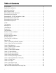
Table of Contents Using the Manual . . . . . . . . . . . . . . . . . . . . . . . . . . . . . . . . . . . . . . . . . . . . . . . . . . . . . . . . . . . . . . . . . . 3 Required Tools and Adhesives . . . . . . . . . . . . . . . . . . . . . . . . . . . . . . . . . . . . . . . . . . . . . . . . . . . . . . . . 3 UltraCote Covering Colors . . . . . . . . . . . . . . . . . . . . . . . . . . . . . . . . . . . . . . . . . . . . . . . . . . . . . . . . . . . 3 Before Starting Assembly . . . . . . . . . . . . . . .
Using the Manual This manual is divided into sections to help make assembly easier to understand, and to provide breaks between each major section. In addition, check boxes have been placed next to each step to keep track of each step completed. Steps with a single box () are performed once, while steps with two boxes ( ) indicate that the step will require repeating, such as for a right or left wing panel, two servos, etc. Remember to take your time and follow the directions.
Radio and Power Systems Requirements • 5-channel radio system (minimum) w/receiver • Large Servo Arm (JSP98060) (for use on flap servos) • 700mAh Ni-Cd 4-cell (JSP91010) • JR Standard Switch (JSP98010) or JR Chargeswitch (JRPA004) • DS821 Digital Sport Servo (JRPS821) (7) or equivalent (6 when building electric version) Recommended Servo Extensions 5-channel Radio System Aileron Y-harness (JSP98020) 9-inch Servo Extension JRPA097 (2) Flaps Y-harness (JSP98020) 6-channel Radio System Aileron Y-harness (JSP9
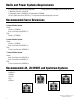
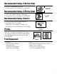
Recommended Setup–2-Stroke Glow • Evolution® .52NX with Muffler (EVOE0520) • Evolution Propeller 11 x 5 (EVO11050) to 11 x 6 (EVO11060) Evolution .52NX EVOE0520 Recommended Setup–4-Stroke Glow • Saito™ .82 AAC w/Muffler (SAIE082A or SAIE082AGK) • Evolution Propeller 13 x 8 (EVO13080) or 14 x 6 (EVO14060) Saito .
Warranty Period Exclusive Warranty- Horizon Hobby, Inc., (Horizon) warranties that the Products purchased (the "Product") will be free from defects in materials and workmanship at the date of purchase by the Purchaser. Limited Warranty (a) This warranty is limited to the original Purchaser ("Purchaser") and is not transferable. REPAIR OR REPLACEMENT AS PROVIDED UNDER THIS WARRANTY IS THE EXCLUSIVE REMEDY OF THE PURCHASER. This warranty covers only those Products purchased from an authorized Horizon dealer.
Questions, Assistance, and Repairs Your local hobby store and/or place of purchase cannot provide warranty support or repair. Once assembly, setup or use of the Product has been started, you must contact Horizon directly. This will enable Horizon to better answer your questions and service you in the event that you may need any assistance. For questions or assistance, please direct your email to productsupport@horizonhobby.com, or call 877.504.0233 toll free to speak to a service technician.
Safety, Precautions, and Warnings This model is controlled by a radio signal that is subject to interference from many sources outside your control. This interference can cause momentary loss of control so it is advisable to always keep a safe distance in all directions around your model, as this margin will help to avoid collisions or injury. • Always operate your model in an open area away from cars, traffic, or people. • Avoid operating your model in the street where injury or damage can occur.
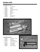
Contents of Kit Large Replacement Parts A. HAN4031 Fuselage w/Hatch B. HAN4032 Right Wing C. HAN4033 Left Wing D. HAN4034 Horizontal Stab and Elevator E. HAN4035 Wing Struts F. HAN4036 Rudder G. HAN4037 Landing Gear H. HAN4038 Wheels I. HAN4039 Cowl J. HAN4040 Canopy with Seat K. HAN4043 Wing Tube Set A J I F D B G C E Small Replacement Parts 1. HAN4041 Assembled 11 oz fuel tank 2. HAN4044 Pushrod Set 3. HAN4045 Glow Motor Mount 4. HAN4046 EP Motor Mount Standoffs 5. HAN4047 Pin and Keeper Set 6.
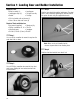
Section 1: Landing Gear and Rudder Installation Required Parts • Wheel assembly (2) • Landing gear • Landing gear strap (4) • Tail gear assembly • Rudder • Fuselage • 5/32-inch wheel collar w/setscrew (2) • 3mm x 10mm sheet metal screw (8) o Step 3 Slide the inner wheel hub onto the landing gear. The wheel collar is then installed by tightening the setscrew onto the flat spot on the axle using the supplied hex wrench.
Section 1: Landing Gear and Rudder Installation o Step 5 o Step 6 Slide the outer wheel hub back into the wheel. Slide the supplied hex wrench into the screw hole in the outer wheel hub, then into the screw hole in the inner wheel hub to aid in aligning the screw holes. Reinstall the four sheet metal screws to secure the inner and outer wheel hubs in the wheel. o Step 7 Snap the cap back in position on the outer wheel hub.
Section 1: Landing Gear and Rudder Installation Step 9 Step 11 Attach the landing gear to the fuselage using four landing gear straps and eight 3mm x 10mm sheet metal screws and a #2 Phillips screwdriver. Apply a small amount of petroleum jelly to the top and bottom of the tail gear bushing. Work the jelly into the bushing to prevent epoxy from entering the bushing and locking the tail gear wire. Step 10 Use sandpaper to roughen the wire so the epoxy will have a rough surface to bond to.
Section 1: Landing Gear and Rudder Installation Step 13 Step 15 Use a pin drill and 1/16-inch (1.5mm) drill bit to drill a hole in the center of each hinge slot in the fin and rudder. This will provide a tunnel for the CA to wick into, providing a better bond between the hinge and surrounding wood. Slide each of the hinges into the rudder until the T-pin is resting on the hinge line of the rudder.
Section 1: Landing Gear and Rudder Installation Step 17 Step 19 As you slide the rudder onto the tail gear wire, slide the hinges for the rudder into the slots in the fin. The rudder should fit tight against the fin, and should not bind at the balance tab when the rudder is in operation. Remove the T-pins from the hinges. Apply thin CA to both sides of the three hinges. Allow the CA to cure (without using accelerator) before proceeding to the following steps.
Section 1: Landing Gear and Rudder Installation Step 21 Step 22 Move the rudder right and left a number of times to condition the hinges. Secure the tail wheel using two 1/16-inch wheel collars and two setscrews. Tighten the setscrews using the supplied hex wrench. Note: Make sure to use threadlock on the setscrews to prevent them from vibrating loose.
Section 2: Aileron and Flap Servo Installation Required Parts • Snap link (4) • Nylon clevis (4) • Clevis retainer (4) • Flap servo cover (right and left) • Aileron servo cover (right and left) • #2 x 3/8-inch sheet metal screw (16) • 3 3/4-inch (95mm) threaded pushrod (4) • Servo mounting blocks, 3/4 x 9/16 x 5/16-inch (19 x 14 x 8mm) (8) ooo Step 2 Position the servo onto the servo cover. The servo horn will be centered and in line with the outer edge of the cover as shown.
Section 2: Aileron and Flap Servo Installation ooo Step 4 ooo Step 6 Lightly sand the servo mounting blocks on the edge where they will be glued to the servo cover. This will allow the epoxy to hold onto the block, providing a more secure bond between the cover and blocks. Transfer the locations for the servo mounting screws onto the servo mounting blocks using a pencil. ooo Step 7 ooo Step 5 Use 30-minute epoxy to attach the two mounting blocks to the servo cover.
Section 2: Aileron and Flap Servo Installation ooo Step 8 oo Step 10a (aileron servos only) Apply 2–3 drops of thin CA into each of the holes to harden the surrounding wood. This will make the screws more secure and prevent them from vibrating loose. Remove the supplied servo arm from the aileron servo. After centering the servo, attach a standard double arm using the screw supplied with the servo. Use side cutters to remove the portion of the arm that does not extend beyond the servo cover.
Section 2: Aileron and Flap Servo Installation ooo Step 11 ooo Step 13 Pass the servo extension through the wing and into the bay for the flap servo. Use four #2 x 3/8-inch sheet metal screws to attach the servo cover to the wing. Use a pin drill and 5/64-inch (2mm) drill bit to enlarge the outermost hole in the servo arm to accept the pushrod wire. ooo Step 12 Continue to pass the aileron extension through the wing. Use tape (or glue) to secure the aileron extension to the top sheeting of the wing.
Section 2: Aileron and Flap Servo Installation ooo Step 15 ooo Step 17 Secure the pushrod wire using one of the snap links provided with your Piper Pawnee 40. Turn on the radio system and plug the aileron servo into the receiver. Attach the clevis to the middle hole of the control horn as shown. It will be necessary to thread the clevis in or out on the pushrod wire to center the control surface while the radio is on and the servo centered.
Section 3: Wing Attachment Required Parts • Wing strut (front) (right and left) • Wing strut (rear) (right and left) • 3mm nut (4) • Strut end (4) • Wing strut bracket (4) • #4 washer (4) • Wing tube (small) • Wing tube (large) • 4-40 lock nut (4) • Retainer pin clip (4) • 1/4-inch (4mm) fuel tubing (4) • Strut attachment pin (4) • 4-40 x 1/2-inch socket head screw (18) Step 2 Thread a strut end onto each of the struts.
Section 3: Wing Attachment Step 4 o Step 6 Attach the fuselage strut brackets using four 4-40 x 1/2-inch socket head screws and four #4 washers. The bracket will angle down and point toward the wing when installed. Slide the wing tubes into the fuselage. Guide the servo leads for the aileron and flap servos into the opening in the fuselage while positioning the wing. Note: Make sure to use threadlock on the screws to prevent them from vibrating loose.
Section 3: Wing Attachment o Step 8 o Step 10 Attach the wing struts to the wing strut brackets using 4-40 x 1/2-inch socket head screws and 4-40 lock nuts. Note that the longer strut is positioned toward the rear (trailing edge) of the wing. Also note the airfoil shape of the strut during the installation. Align the holes at the ends of the struts with the holes in the fuselage bracket. It will be necessary to adjust the length of the strut ends to attach the struts without forcing them into position.
Section 3: Wing Attachment o Step 11 o Step 12 Attach the struts to the fuselage strut brackets using two strut attachment pins and two retainer pin clips. Once the length of the struts has been set, make sure to use threadlock on the nuts and strut ends to prevent them from vibrating loose. Also tighten the 3mm nut against the strut end to lock everything into position.
Section 4: Stabilizer/Elevator Installation Required Parts • Stabilizer/elevator (right and left) • 4-40 x 1/2-inch socket head screws (10) • #4 washers (4) • 4-40 lock nut (4) • Tail rigging (long tab) (2) • Tail rigging tab (8) • Tail rigging (medium tab) (2) • Tail rigging (short tab, short cable) (4) • 1 3/16-inch (30mm) pin • 13/16-inch (21mm) pin Step 2 Attach one half of the stabilizer using two 4-40 x 1/2-inch socket head screws and two #4 washers.
Section 4: Stabilizer/Elevator Installation Step 4 Step 6 Attach the tail rigging with the long and medium tabs to the bottom of the fuselage using two #2 x 1/2-inch sheet metal screws. The longest tabs go to the front, while the medium length tabs go to the rear. Attach the tabs to the top and bottom of the stabilizer using four 4-40 x 1/2-inch socket head screws and four 4-40 lock nuts. Leave the bolts loose enough so the tabs can be rotated.
Section 4: Stabilizer/Elevator Installation Step 7 Step 9 Connect the rigging to the tabs on the stabilizer. Once all the cables have been attached, go back and tighten the bolts holding the tabs at the stabilizer. Do not crush the wood of the stabilizer by over-tightening the screws. Step 10 Adjust the flying wires so there is equal and light tension on each wire. Make sure that the stabilizer and fin have not been twisted during the tensioning of the flying wires.
Section 5: Radio Installation Required Parts • Fuselage assembly • Servo w/hardware (2) • Receiver • Receiver battery • Switch harness • Foam rubber • Y-harness (2) • Hook and loop strap • Nylon clevis (3) • Clevis retainer (3) • Snap link (2) • 5/32-inch wheel collar (2) • 32-inch (813mm) pushrod • 31 1/4-inch (794mm) pushrod • 32 1/2-inch (825mm) pushrod • 3mm x 8mm machine screw (2) Required Tools and Adhesives • Pin drill • Thin CA • Phillips screwdriver: #1, #2 • 30-minute epoxy • Drill bit: 1/16-inch
Section 5: Radio Installation o Step 4 Step 6 Use the screws supplied with the servo and a #1 Phillips screwdriver to secure the servo to the radio tray. Wrap the receiver battery in foam and secure it to the radio tray using the supplied hook and loop strap. The receiver is mounted on the battery and should be positioned to avoid vibrations from being transferred through the airframe into the receiver. Install your switch harness at this time as well.
Section 5: Radio Installation o Step 8 32 1/2-inch Slide the (825mm) pushrod into the pushrod tube for the rudder. It is easiest to start by inserting the pushrod in the opening in the firewall to prevent bending it around the fuselage structure. o Step 9 Replace the standard servo arm on the elevator servo with a standard double arm. Use a 5/64-inch (2mm) drill bit and pin drill to enlarge the outer hole in the rudder servo arm.
Section 5: Radio Installation Step 12 Step 14 Slide the two 5/32-inch wheel collars onto the 32-inch (813mm) elevator pushrod. Secure the collars near the bend using a 3mm x 8mm machine screw and #2 Phillips screwdriver. The wheel collars will be positioned later. Thread a clevis on the remaining 31 1/4-inch (794mm) pushrod. Slide the pushrod into the pushrod tube from outside the fuselage and attach the clevis to the center hole of the elevator control horn.
Section 6: 2-Stroke Engine Installation Required Parts • Engine mount • 8-32 lock nut (4) • Clevis • Clevis retainer • Engine mount plate (2) • Fuel tank 3 • 11 /4-inch (300mm) throttle pushrod tube • 8-32 x 3/4-inch machine screw (4) • 8-32 x 1-inch machine screw (4) • 17 3/4-inch (450mm) throttle pushrod Step 2 Temporarily install the rear 8-32 x 1-inch machine screws and 8-32 lock nuts to attach the mounting plates to the mount. Finger-tighten the screws at this time.
Section 6: 2-Stroke Engine Installation Step 4 Step 6 Use a pencil to mark the location of the throttle pushrod tube on the firewall. Roughen the outside of the 11 3/4-inch (300mm) throttle pushrod tube using sandpaper. Slide the tube into the hole, leaving around 1-inch (25mm) of the tube forward of the firewall. Step 5 Use a drill and 11/64-inch (4.5mm) drill bit to drill the hole for the throttle pushrod tube.
Section 6: 2-Stroke Engine Installation Step 8 Step 10 Slide a clevis retainer onto a clevis, then thread the clevis onto the 17 3/4-inch (450mm) throttle pushrod. Attach the muffler to your engine following the instructions provided with your particular engine. Step 9 Step 11 Slide the pushrod into the tube and connect the clevis to the carburetor arm. Look carefully at the fuel tank to determine which tubes are for the carburetor and vent.
Section 6: 2-Stroke Engine Installation Step 12 Step 14 Slide the tank into the fuselage, making sure the vent line faces toward the top of the fuselage. Connect the lines from the fuel tank to the engine and muffler. We used a fuel dot to allow fueling the tank from outside the cowling. Step 13 Install a brace and foam padding around the fuel tank to keep it in position inside the fuselage and protect it from vibration.
Section 7: 4-Stroke Installation Required Parts • Engine mount • 8-32 lock nut (4) • Engine mount plate (2) • Fuel tank 3 • 11 /4-inch (300mm) throttle pushrod tube • 8-32 x 3/4-inch machine screw (4) • 8-32 x 1-inch machine screw (4) • 17 3/4-inch (450mm) throttle pushrod Step 2 Temporarily install the rear 8-32 x 1-inch machine screws and 8-32 lock nuts to attach the mounting plates to the mount. Finger-tighten the screws at this time.
Section 7: 4-Stroke Installation Step 4 Step 6 Slide the engine between the mount and mounting plates. Install the remaining 8-32 x 1-inch machine screws and 8-32 lock nuts at the front of the mounting plates. Remove the engine from the engine mount. Use a drill and 11/64-inch (4.5mm) drill bit to drill the hole for the throttle pushrod tube. Step 5 Step 7 Use a pencil to mark the location of the throttle pushrod tube on the firewall.
Section 7: 4-Stroke Installation Step 8 Step 10 Use side cutters to trim the pushrod tube as shown. Attach the Z-bend to the carburetor by inserting the Z-bend in the outer hole of the carburetor arm as shown. Step 9 Make a Z-bend in the 17 3/4-inch (450mm) throttle pushrod. Make the bend on the end without the threads. 38 Step 11 Slide the engine back into position on the mounts. (See Step 4 for details.) Position the engine so the drive washer is 4 5/8-inch (118mm) forward of the firewall.
Section 7: 4-Stroke Installation Step 12 Step 14 Attach the muffler to your engine following the instructions provided with your particular engine. Slide the tank into the fuselage, making sure the vent line faces toward the top of the fuselage. Step 13 Step 15 Look carefully at the fuel tank to determine which tubes are for the carburetor and vent. Also check the direction of the vent line inside the fuel tank. The vent will face the top of the fuselage when the fuel tank is installed.
Section 7: 4-Stroke Installation Step 16 Connect the lines from the fuel tank to the engine and muffler. We used a fuel dot to allow fueling the tank from outside the cowling.
Section 8: Throttle Servo Installation Required Parts • Fuselage assembly • Servo • Snap link • Plywood pushrod standoff Step 3 Use a felt-tipped pen to mark the pushrod where it crosses the outer hole on the servo horn. Required Tools and Adhesives • Pencil • Thin CA • Drill bit: 5/64-inch (2mm) • Pliers • Side cutters • Pin drill • Phillips screwdriver • Medium CA Step 1 Slide the plywood pushrod standoff onto the pushrod tube.
Section 8: Throttle Servo Installation Step 5 Step 7 Use a pin drill and a 5/64-inch (2mm) drill bit to enlarge the outer hole in the servo arm. Slide the pushrod wire through the hole in the servo horn. Slide the snap link onto the pushrod wire, then rotate it until it snaps onto the wire. Slide the plywood pushrod standoff so it can be glued to the side of the fuselage using medium CA as shown. Step 6 Use side cutters to remove the excess wire. Leave at least 1/16-inch (1.
Section 9: Electric Motor Installation Required Parts • Fuselage assembly • Motor w/hardware • Electronic speed control • Hook and loop strap • Hook and loop tape •Motor battery • 2-inch (50mm) aluminum standoff (4) • 8-32 x 2 1/2-inch (64mm) machine screw (4) Step 2 Use a hobby knife and a covering iron to open the cooling air exit in the bottom of the fuselage.
Section 9: Electric Motor Installation Step 4 Step 6 Attach the X-mount to the motor using the screws provided with the motor. Secure the speed controller to the bottom of the fuselage using hook and loop tape as shown. Secure the wires between the motor and speed control so they do not interfere with the operation of the motor. Note: Make sure to use threadlock on the screws to prevent them from vibrating loose.
Section 10: Cowling and Canopy Installation Required Parts • Fuselage assembly • Cowling • 1/4-inch (4mm) tubing (4) • #4 washer (4) • Spinner w/hardware • Canopy • Pilot seat • 4-40 x 1/2-inch socket head screws Step 2 Secure the cowling to the fuselage using the screws prepared in the previous step.
Section 10: Cowling and Canopy Installation Step 4 Step 5 Use the following images as a guide for cutting the cowling for a 4-stroke engine. Make sure to make cutouts for the rocker box covers, exhaust and needle valve. You will need to drill a 3/8-inch (9.5mm) hole in the cowl for mounting the fuel dot as well. Use the following images as a guide for cutting the cowling for a 2-stroke engine. Make sure to make cutouts for glow plug access, muffler and needle valve.
Section 10: Cowling and Canopy Installation Step 6 Step 7 Use medium CA to glue the pilot seat in the cockpit. Note that the seat does fit slightly forward of the rear of the cockpit as shown. Use canopy glue to secure the canopy to the fuselage. Use low-tack tape to hold the canopy in position until the glue fully cures. If you are planning on installing a pilot figure then install now before attaching the canopy.
Section 12: Control Throws The amount of control throw should be adjusted as closely as possible using mechanical means, rather than making large changes electronically at the radio. By moving the position of the clevis at the control horn toward the outermost hole, you will decrease the amount of control throw of the control surface. Moving it toward the control surface will increase the amount of throw.
Section 13: Pre-Flight Charge both the transmitter and receiver pack for your airplane. Use the recommended charger supplied with your particular radio system, following the instructions provided with the radio. In most cases, the radio should be charged the night before going out flying. Check the radio installation and make sure all the control surfaces are moving correctly (i.e. the correct direction and with the recommended throws).
2008 Official AMA National Model Aircraft Safety Code GENERAL 1. A model aircraft shall be defined as a non-humancarrying device capable of sustained flight in the atmosphere. It shall not exceed limitations established in this code and is intended to be used exclusively for recreational or competition activity. 2. The maximum takeoff weight of a model aircraft, including fuel, is 55 pounds, except for those flown under the AMA Experimental Aircraft Rules. 3.
2008 Official AMA National Model Aircraft Safety Code Radio Control 1. All model flying shall be conducted in a manner to avoid over flight of unprotected people. 2. I will have completed a successful radio equipment ground-range check before the first flight of a new or repaired model aircraft. 3. I will not fly my model aircraft in the presence of spectators until I become a proficient flier, unless I am assisted by an experienced pilot. 4.
© 2008 Horizon Hobby, Inc. 4105 Fieldstone Road Champaign, Illinois 61822 (877) 504-0233 horizonhobby.