
User manual
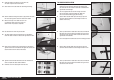
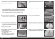
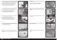

5. Slide the axle wing on the gear legs. The struts may need
repositioning to properly fi t the wing.
6. Apply a drop of thread lock on four M3 x 10 button head screws.
Thread the screws through the gear legs and into the pre-installed
blind nuts in the wing. Leave the screws loose for the following step.
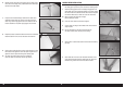
8. Remove the axle supports. File a 1/4-inch (6mm) fl at area on the
axle supports that are 13/32 inch (10mm) and 2
1
/
16
inches (52mm)
from each end of the axle support. Make sure to position the fl at
areas perpendicular to the holes in the axle support.
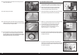
9. Slide the axle supports back into position. Place two wheel collars on
the end of the axle support as shown.
7. Slide the two steel axle supports into the wing and through the holes
in the landing gear legs. The screws from the previous step can now
be tightened using a 2mm hex wrench.
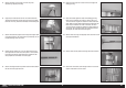
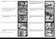
10. Position the axle support so it is fl ush with the outer edge of the
landing gear wing.
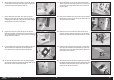
11. Slide a wheel collar against the inside of the landing gear wing.
Place a drop of thread lock on the M3 x 3 setscrew, then use a
1.5mm hex wrench to tighten the setscrew on the fl at area made
earlier. Slide the second wheel collar against the landing gear strut.
Place a drop of thread lock on an M3 x 3 setscrew, then use a
1.5mm hex wrench to tighten the setscrew on the fl at area of the
axle support. Secure the wheel collars on the opposite end of the
axle support, then install the second axle support.
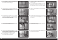
13. Slide the main axle into position and through the shock cord collar.
14. Slide an M3 x 40 machine screw through the hole in the rear axle
support. Thread an M3 nut on the screw.
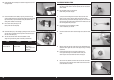
12. Mark the main axle using a felt-tipped pen so the notch ion the axle
can easily be located later.
23 EN
Fokker D.VII 30–60cc ARF