
User manual

ELECTRIC MOTOR INSTALLATION
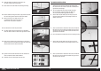
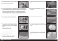
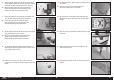
1. Place the mounting template on the fi rewall. Use low-tack tape to
hold the template in position. Use a drill and 3/32-inch (2.5mm) drill
bit to drill the four holes in the fi rewall to attach the motor box.
When using power systems other than the recommended
choices, we advise using the mounting template as a test
to ensure hole alignment before drilling the firewall.
2. Remove the template from the fuselage. Use a drill and 13/64-inch
(5mm) drill bit to enlarge the holes from the previous step.
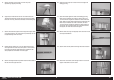
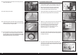
4. Use a square to check the horizontal position the motor fi rewall in
the motor box. Use the line drawn in the previous step to position the
front edge of the fi rewall.
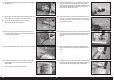
5. Use a square to check the vertical position of the fi rewall. Once
positioned, use a felt-tipped pen to mark the position of the fi rewall
on all sides of the motor box. Mark the inside of the box to indicate
the location to apply epoxy.
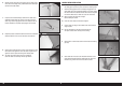
3. Measure 3
13
/
16
inches (97.2mm) from the rear of the motor box and
use a felt-tipped pen and square to draw a line on the box.
The measurement is for the recommended Rimfire 65cc
electric motor (GPMG4805). When using other motors,
the distance from the rear of the motor box to the drive
washer must measure 7
11
/
16
inches (195mm).
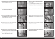
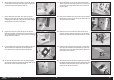
34. Use a rotary tool and cut-off wheel to trim the tubing at the mark
made in the previous step.
35. Slide the tubing into the wheel.
36. Check that the tubing is fl ush with the wheel on both sides before
installing the wheel on the axle. Use a fl at fi le to remove any fl ashing
from the tubing or alter its length if needed.
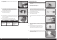
37. Secure the wheels to the main axle using the wheel collars and
M3 x 3 setscrews. The wheel collars are placed on either side of
the wheel. Make sure to use a fi le to make a fl at area on the main
axle for the setscrews. Apply a drop of threadlock on each setscrew
before tightening them using a 1.5mm hex wrench.
26EN