
User manual
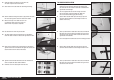
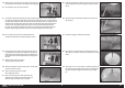
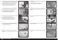

6. Place the mounting template on the fi rewall. Use low-tack tape to
hold the template in position. Use a drill and 3/32-inch (2.5mm) drill
bit to drill the four holes in the fi rewall to attach the motor box.
When using power systems other than the recommended
choices, we advise using the mounting template as a test
to ensure hole alignment before drilling the firewall.
7. Remove the template from the fuselage. Use a drill and 9/32-inch
(7mm) drill bit to enlarge the holes from the previous step.
Drilling increasingly larger holes allows the ability to
check the alignment of engine mounting holes. It also
helps reduce splintering of the firewall material.
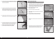
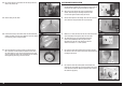
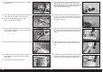
9. Use medium grit sandpaper to roughen the outside edge of the
throttle pushrod tube. Cut the tube to a length of 7 inches (178mm)
using a hobby knife and #11 blade
10. Insert the tube in the hole. Leave 1/4-inch (6mm) of the tube
protruding from the fi rewall. Use medium CA to glue the tube in the
fi rewall.
8. Use the template to locate and drill the hole for the throttle pushrod
using a drill and 9/64-inch (3.5mm) drill bit.
Make sure the throttle tube location matches the engine
selection. It may be necessary to drill the hole in a
different location than recommended by the template.
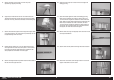
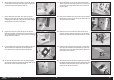
11. Use a hobby knife and #11 blade to remove the covering for the fuel
tank overfl ow.
There are two choices for the overflow location in the
bottom of the fuselage. Open only one location.
12. Secure the fuel tank in the fuselage using hook and loop straps.
Use foam rubber under the tank to keep it from moving inside the
fuselage.
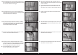
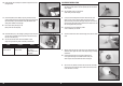
14. Route the overfl ow through the hole in the fuselage and fi t the
overfl ow fi tting to the tube.
15. Slide the fi tting into position. Use the nut to secure the fi tting in the
fuselage.
13. Slide a nut from the fuel overfl ow on the overfl ow tube coming from
the fuel tank.
29 EN
Fokker D.VII 30–60cc ARF