
User's Manual


3. Module Interface
3.1. PIN Definitions
PIN PIN NAME DESCRIPTION TYPE NOTE
Pin1 UART0_TX UART0 send data O
UART0
Only used for UART
DCDC works when EN >
1.5V
Pin2 UART0_RX UART0 receive data I
Pin3 EN Enable DCDC I
Pin4 GND GND POWER
Pin5 VDD Power input POWER
1. The TX and RX of UART0 are used for communication with external processor. Please
refer to Chapter 2.3 DC Characteristics for more information of output power level for
UART.
2. The module has built-in RC reset and watchdog circuit.
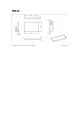
3.2. PCB Antenna
The module supports PCB antenna. Within the range of 2.4-2.5GHz, the antenna output S11 is
less than -10dB and gain of antenna is about 2dBi.