Camera Network Bullet Camera Quick Start Guide UD 0
Network Bullet Camera· ·Quick Start Guide Quick Start Guide COPYRIGHT ©2016 Hangzhou Hikvision Digital Technology Co., Ltd. ALL RIGHTS RESERVED. Any and all information, including, among others, wordings, pictures, graphs are the properties of Hangzhou Hikvision Digital Technology Co., Ltd. or its subsidiaries (hereinafter referred to be “Hikvision”).
Network Bullet Camera· ·Quick Start Guide Legal Disclaimer TO THE MAXIMUM EXTENT PERMITTED BY APPLICABLE LAW, THE PRODUCT DESCRIBED, WITH ITS HARDWARE, SOFTWARE AND FIRMWARE, IS PROVIDED “AS IS”, WITH ALL FAULTS AND ERRORS, AND HIKVISION MAKES NO WARRANTIES, EXPRESS OR IMPLIED, INCLUDING WITHOUT LIMITATION, MERCHANTABILITY, SATISFACTORY QUALITY, FITNESS FOR A PARTICULAR PURPOSE, AND NON-INFRINGEMENT OF THIRD PARTY.
Network Bullet Camera· ·Quick Start Guide IN THE EVENT OF ANY CONFLICTS BETWEEN THIS MANUAL AND THE APPLICABLE LAW, THE LATER PREVAILS. Regulatory Information FCC Information Please take attention that changes or modification not expressly approved by the party responsible for compliance could void the user’s authority to operate the equipment. FCC compliance: This equipment has been tested and found to comply with the limits for a Class B digital device, pursuant to part 15 of the FCC Rules.
Network Bullet Camera· ·Quick Start Guide FCC Conditions This device complies with part 15 of the FCC Rules. Operation is subject to the following two conditions: 1. This device may not cause harmful interference. 2. This device must accept any interference received, including interference that may cause undesired operation.
Network Bullet Camera· ·Quick Start Guide supplier or to a designated collection point. For more information see: www.recyclethis.info Industry Canada ICES-003 Compliance This device meets the CAN ICES-3 (B)/NMB-3(B) standards requirements. This device complies with Industry Canada licence-exempt RSS standard(s).
Network Bullet Camera· ·Quick Start Guide fonctionner avec une antenne d'un type et d'un gain maximal (ou inférieur) approuvé pour l'émetteur par Industrie Canada. Dans le but de réduire les risques de brouillage radioélectrique à l'intention des autres utilisateurs, il faut choisir le type d'antenne et son gain de sorte que la puissance isotrope rayonnée équivalente (p.i.r.e.) ne dépasse pas l'intensité nécessaire à l'établissement d'une communication satisfaisante.
Network Bullet Camera· ·Quick Start Guide Warnings ● Proper configuration of all passwords and other security settings is the responsibility of the installer and/or end-user. ● In the use of the product, you must be in strict compliance with the electrical safety regulations of the nation and region. Please refer to technical specifications for detailed information.
Network Bullet Camera· ·Quick Start Guide ● Do not touch sensor modules with fingers. If cleaning is necessary, use clean cloth with a bit of ethanol and wipe it gently. If the camera will not be used for an extended period, please replace the lens cap to protect the sensor from dirt. ● Do not aim the camera at the sun or extra bright places. Blooming or smearing may occur otherwise (which is not a malfunction), and affect the endurance of sensor at the same time.
Network Bullet Camera· ·Quick Start Guide ● Improper use or replacement of the battery may result in hazard of explosion. Replace with the same or equivalent type only. Dispose of used batteries according to the instructions provided by the battery manufacturer. ● If the product does not work properly, please contact your dealer or the nearest service center. Never attempt to disassemble the camera yourself. (We shall not assume any responsibility for problems caused by unauthorized repair or maintenance.
Network Bullet Camera· ·Quick Start Guide Table of Contents 1 Appearance Description ............................................................... 11 1.1 Overview of Type I Bullet Camera ................................. 11 1.2 Overview of Type II Bullet Camera ................................ 13 1.2.1 Installing the microSD Card ................................ 15 1.2.2 Resetting the Camera ......................................... 15 1.2.3 Setting the WPS Protocol....................................
Network Bullet Camera· ·Quick Start Guide 1 Appearance Description 1.
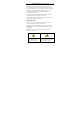
Network Bullet Camera· ·Quick Start Guide Table 1-1 Description No. Description No. Description 1 Mounting Base 4 Lens 2 Back Box 5 Sun Shield 3 Front Box 6 Power Cable 7 Reset Button 8 GND Screw 9 10/100M Self-adaptive Ethernet Interface Type I camera does not support the function of Wi-Fi or micorSD card. Press Reset button about 10s when the camera is power on or rebooting to restore the default settings, including the user name, password, IP address, port No., etc.
Network Bullet Camera· ·Quick Start Guide 1.2 Overview of Type II Bullet Camera Figure 1-2 Type II Bullet Camera Table 1-2 Description No. Description No.
Network Bullet Camera· ·Quick Start Guide No. Description No. Description 3 Sun Shield 9 10/100M Self-adaptive Ethernet Interface 4 Lens 10 PoE Cable 5 Adjusting Nut 11 GND Screw 6 WPS/RESET Button This type of bullet camera supports PoE power supply. You can power the camera by connecting both DC 12V interface and the Ethernet interface. Or you can connect the Ethernet interface only.
Network Bullet Camera· ·Quick Start Guide WPS function and Reset function share the same button. The button works as a reset button only when you press it when the camera is powered on. 1.2.1 Installing the microSD Card Insert the microSD card into the microSD card slot. Figure 1-4 Installing the microSD Card 1.2.2 Resetting the Camera Press WPS/RESET button about 10s when the camera is power on or rebooting to restore the default settings, including the user name, password, IP address, port No., etc.
Network Bullet Camera· ·Quick Start Guide Figure 1-5 WPS/RESET Button 1.2.3 Setting the WPS Protocol A wireless router with the WPS function is required to enable the WPS function of the camera. Refer the steps below. Steps: 1. Enable the WPS function of your router. Refer to the operation guide of your router for detailed procedures. 2. Press the WPS/RESET button (about 2s) on the camera to join in the wireless network.
Network Bullet Camera· ·Quick Start Guide Figure 1-6 WPS/RESET Button You can also press the WPS button on the camera first and then enable the WPS function on the router to establish the connection. But the WPS function of the router must be turned on within 120s right after pressing the WPS/RESET button on the camera. Screw the microSD/RESET/WPS Cover back to the camera after all the settings.
Network Bullet Camera· ·Quick Start Guide 2 Installation Before you start: ● Make sure the device in the package is in good condition and all the assembly parts are included. ● The standard power supply is 12V DC or 24V AC, please make sure your power supply matches with your camera. ● Make sure all the related equipment is power-off during the installation. ● Check the specification of the products for the installation environment.
Network Bullet Camera· ·Quick Start Guide 2.1 Installation of the Bullet Camera Both wall mounting and ceiling mounting are suitable for the bullet camera. Wall mounting will be taken as an example in this section. You can take steps of wall mounting for reference if ceiling mounting is adopted. Steps: 1. Drill the screw holes in the wall according to the drill template. Figure 2-1 Drill Template 2. Route the corresponding cables. 3. Secure the camera to the wall with the supplied Screws.
Network Bullet Camera· ·Quick Start Guide Figure 2-2 Secure the Camera to the Ceiling 4. Connect the corresponding power/Video Output cables. 5. Adjust the surveillance angle. Figure 2-3 3-axis Adjustment 1). Loosen the adjusting nut. 2). Adjust the pan direction [0° to 360°]. 3). Adjust the tilt direction [0° to 90°].
Network Bullet Camera· ·Quick Start Guide 4). Rotate the camera [0° to 360°] to adjust the lens to the desired surveillance angle. 5). Tighten the adjusting nut to complete the installation.
Network Bullet Camera· ·Quick Start Guide 2.2 Installation of Network Cable Water-proof Jacket (Optional) Purpose: If the camera is installed outdoor, you can adapt the water-proof accessory for the network cable after the camera is secured on the installation surface. Figure 2-4 Water-proof Accessory Components Table 2-1 Components No.
Network Bullet Camera· ·Quick Start Guide Figure 2-5 Water-proof Accessory Installation Steps: 1. Feed the plugless network cable ⑦ through the lock nut ⑥, waterproof rubber gasket ⑤ (rubber gasket inset ridge must face waterproof endcap), and the water-proof endcap ④ in order. 2. Crimp an RJ-45 network plug ③onto the end of the cable, taking care to insert the twisted pairs of wires in correct order. 3. Place the O-type gasket ② onto the end of the camera’s network interface socket ①.
Network Bullet Camera· ·Quick Start Guide 4. Insert the network plug ③ into the camera’s network interface socket①. 5. Insert the water-proof rubber gasket ⑤ into the waterproof endcap ④, and secure lock nut ⑥ with the water-proof endcap ④. 6. Align the snap on the water-proof endcap ④ with the notch on the camera’s network interface socket ①, and then secure the water-proof endcap ④ to the camera’s network interface socket ① to finish installation.
Network Bullet Camera· ·Quick Start Guide 3 Setting the Network Camera over the LAN Note: You shall acknowledge that the use of the product with Internet access might be under network security risks. For avoidance of any network attacks and information leakage, please strengthen your own protection. If the product does not work properly, please contact with your dealer or the nearest service center. 3.
Network Bullet Camera· ·Quick Start Guide 3.2 Activating the Camera You are required to activate the camera first by setting a strong password for it before you can use the camera. Activation via Web Browser, Activation via SADP, and Activation via Client Software are all supported. We will take activation via SADP software and Activation via Web Browser as examples to introduce the camera activation. Please refer to the User Manual of Network Camera for Activation via Client Software. 3.2.
Network Bullet Camera· ·Quick Start Guide 3. Create a password and input the password into the password field. STRONG PASSWORD RECOMMENDED– We highly recommend you create a strong password of your own choosing (using a minimum of 8 characters, including upper case letters, lower case letters, numbers, and special characters) in order to increase the security of your product.
Network Bullet Camera· ·Quick Start Guide Figure 3-4 SADP Interface Note: The SADP software supports activating the camera in batch. Please refer to the user manual of SADP software for details. 3. Create a password and input the password in the password field, and confirm the password.
Network Bullet Camera· ·Quick Start Guide 4. Click OK to save the password. You can check whether the activation is completed on the popup window. If activation failed, please make sure that the password meets the requirement and try again. 3.3 Modifying the IP Address Purpose: To view and configure the camera via LAN (Local Area Network), you need to connect the network camera in the same subnet with your PC. Then, install the SADP software or client software to search and change the IP of network camera.
Network Bullet Camera· ·Quick Start Guide Figure 3-5 Modify the IP Address 4. Input the password to activate your IP address modification. The batch IP address modification is supported by the SADP; please refer to the User Manual of SADP for details.
Network Bullet Camera· ·Quick Start Guide 4 Accessing via Web Browser System Requirement: Operating System: Microsoft Windows XP SP1 and above version CPU: 2.0 GHz or higher RAM: 1G or higher Display: 1024×768 resolution or higher Web Browser: Internet Explorer 8.0 and above version, Apple Safari 5.0.2 and above version, Mozilla Firefox 5.0 and above version and Google Chrome 18 and above version Steps: 1. Open the web browser. 2.
Network Bullet Camera· ·Quick Start Guide 4. Click Login. Figure 4-1 Login Interface 5. Install the plug-in before viewing the live video and managing the camera. Please follow the installation prompts to install the plug-in. Note: You may have to close the web browser to finish the installation of the plug-in. Figure 4-2 Download Plug-in 6. Reopen the web browser after the installation of the plug-in and repeat steps 2 to 4 to login.
0