
User Manual


5
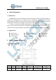
4. Reference Design
4.1.Announcements
The power supply wiring is as thick as possible. It is suggested that the design can
provide 500mA current.
Radio frequency interface to
the antenna solder part line as short as possible, to 50 Ω
impedance matching, walk around the line played more holes.
The module reset pin suggests that the external environment may cause the module
reset by connecting the MCU for control.
SPI port and DIO port can add pull resistor as needed.
DIO port should be connected to IO port with external interrupt of MCU as possible.
Clearance is required around the antenna, it is recommended to set aside a clearance
area of 5mm.
If permitted, the PI circuit is added to the part of the RF outlet to the antenna pad.
The module of FHSS only uses the private protocol of LoRa. The DTS part uses LoRaWAN;
The module does not support hybrid system mode.