BT2S Module Datasheet Device Development > Module > Bluetooth Module Version: 20200420 Online Version
BT2S Module Datasheet Contents Contents 1 Product Overview 1.1 Features . . . . . . . . . . . . . . . . . . . . . . . . . . . . . . . . . 1.2 Applications . . . . . . . . . . . . . . . . . . . . . . . . . . . . . . . 1 1 1 2 Change History 2 3 Module Interfaces 3.1 Dimensions and Footprint . . . . . . . . . . . . . . . . . . . . . . . . 3.2 Interface Pin Definition . . . . . . . . . . . . . . . . . . . . . . . . . 3 3 4 4 Electrical Parameters 4.1 Absolute Electrical Parameters . . . . . . . . . . .
BT2S Module Datasheet 1 PRODUCT OVERVIEW 1 Product Overview BT2S is an embedded Bluetooth low energy (BLE) module that Tuya has developed. It consists of a highly integrated Bluetooth chip (TLSR8250F512ET32) and several peripheral components, with an embedded Bluetooth network protocol stack and robust library functions. BT2S also contains a low-power 32-bit multipoint control unit (MCU), BLE 5.0 component, 2.4 GHz radio component, 4 Mbits flash memory, 48 KB static random-access memory (SRAM). 1.
BT2S Module Datasheet 2 CHANGE HISTORY 2 Change History Date Change Description Version After Change 2020/04/20 This is the first release. V1.0.
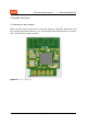
BT2S Module Datasheet 3 MODULE INTERFACES 3 Module Interfaces 3.1 Dimensions and Footprint BT2S has two rows of pins with a 2 mm pin spacing. The BT2S dimensions are 15±0.35mm (W)×18±0.35mm (L) ×2.9±0.15mm(H),The PCB thickness is 0.8±0.1 mm. The BT2S pins show as below Figure 1: BT2S 正面图.
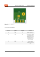
BT2S Module Datasheet 3 MODULE INTERFACES Figure 2: BT2S 反面图.png 3.2 Interface Pin Definition Pin No.
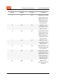
BT2S Module Datasheet 3 MODULE INTERFACES Pin No.
BT2S Module Datasheet 3 MODULE INTERFACES Pin No. Symbol I/O Type Function 11 B4 I/O Common I/O, which can be used as a PWM output of the LED drive and is connected to pin PB4 on the IC Note: 1. P indicates power supply pins, I/O indicates input/output pins, and AI indicates analog input pins. 2. If you have special requirements for light colors controlled by PWM outputs, contact Tuya business personnel.
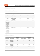
BT2S Module Datasheet 4 ELECTRICAL PARAMETERS 4 Electrical Parameters 4.1 Absolute Electrical Parameters Parameter Description Minimum Value Maximum Value Unit Ts Storage temperature -65 150 ℃ VCC Power supply voltage -0.3 3.9 V Static electricity voltage (human body model) TAMB-25℃ - 2 KV Static electricity voltage (machine model) TAMB-25℃ - 0.5 KV 4.
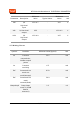
BT2S Module Datasheet 4 Minimum Value ELECTRICAL PARAMETERS Typical Value Maximum Value Unit Parameter Description VIH I/O high-level input VCC*0.7 - VCC V VOL I/O low-level output VSS - VCC*0.1 V VOH I/O high-level output VCC*0.9 - VCC V 4.3 Working Current Symbol Condition Minimum Value(Typical) Unit Itx Constant transmission, 10dBm output power 23.5 mA Irx Constant receiving 6.5 mA IDC Connected to a mesh network(Average) 6.
BT2S Module Datasheet 4 Symbol Ideepsleep2 ELECTRICAL PARAMETERS Condition Minimum Value(Typical) Unit Deep sleep mode 2 (No RAM is reserved.) 0.
BT2S Module Datasheet 5 RF FEATURES 5 RF Features 5.1 Basic RF Features Parameter Description Frequency band 2.4GHz ISM band Wireless standard BLE 4.2/5.0 Data transmission rate 1Mbps,2Mbps Antenna type Onboard PCB antenna 5.2 RF Output Power Parameter Minimum Value Typical Value Maximum Value Unit Average RF output power -21 10 11.5 dBm 20 dB modulation signal bandwidth (1 Mbit/s) - 2500 - KHz 20 dB modulation signal bandwidth (2 Mbit/s) - 1400 - KHz 5.
BT2S Module Datasheet 5 RF FEATURES Parameter Minimum Value Typical Value Maximum Value Unit RX sensitivity 1Mbps - -94 - dBm RX sensitivity 2Mbps - -91 - dBm Frequency offset 1Mbps -250 - +300 KHz Frequency offset 2Mbps -300 - +200 KHz Co-channel interference suppression - -10 - dB 11 / 21
BT2S Module Datasheet 6 ANTENNA INFORMATION 6 Antenna Information 6.1 Antenna Type BT2S uses an onboard PCB antenna. 6.2 Antenna Interference Reduction To ensure optimal RF performance, it is recommended that the antenna be at least 15 mm away from other metal parts. If metal materials are wrapped around the antenna, the wireless signals will be reduced greatly, deteriorating the RF performance. Because BT2S is inserted to the PCB, sufficient space needs to be reserved for the antenna.
7 Packaging Information and Production Instructions 7 Packaging Information and Production Instructions 7.1 Mechanical Dimensions Figure 3: BT2S 尺寸图.png Note: The default dimensional tolerance is ±0.35 mm, and the tolerance for some measurements is ±0.1 mm. If a customer has other requirements, clearly specify them in the datasheet after communication. 7.2 Production Instructions 1.
7 Packaging Information and Production Instructions firmware is burned. If not, vacuum pack the module again. Bake the module before mounting components to the module. A. SMT placement equipment a) Reflow soldering machine b) Automated optical inspection (AOI) equipment c) Nozzle with a 6 mm to 8 mm diameter B. Baking equipment d) Cabinet oven e) Anti-static heat-resistant trays f) Anti-static heat-resistant gloves 2. Storage conditions for a delivered module are as follows: 1 2 3 A.
7 Packaging Information and Production Instructions hours. D. If the 30%, 40%, and 50% circles are pink, bake the module for 12 consecutive hours. 4. Baking settings: A. Baking temperature: 125±5°C B. Alarm temperature: 130°C C. SMT placement ready temperature after natural cooling: < 36°C D. Number of drying times: 1 E. Rebaking condition: The module is not soldered within 12 hours after baking. 5. Do not use SMT to process modules that have unpacked for over three months.
7 PACKAGING INFORMATION AND PRODUCTION INSTRUCTIONS Figure 5: image.
7 PACKAGING INFORMATION AND PRODUCTION INSTRUCTIONS Figure 6: image.
7 PACKAGING INFORMATION AND PRODUCTION INSTRUCTIONS 7.4 Storage Conditions Figure 7: 储存条件.
BT2S Module Datasheet 8 MOQ AND PACKING INFORMATION 8 MOQ and Packing Information Product MOQ Model (pcs) BT2S - Packing Method Number of Modules in Each Reel Pack Number of Reel Packs in Each Box Carrier tape and reel packing - 4 19 / 21
BT2S Module Datasheet 9 APPENDIX: STATEMENT 9 Appendix: Statement FCC Caution: Any changes or modifications not expressly approved by the party responsible for compliance could void the user’s authority to operate this equipment. This device complies with Part 15 of the FCC Rules.Operation is subject to the following two conditions: (1) This device may not cause harmful interference, and (2) this device must accept any interference received, including interference that may cause undesired operation.
BT2S Module Datasheet 9 APPENDIX: STATEMENT end product must be labeled in a visible area with the following: “Contains Transmitter Module FCC ID: 2ANDL-BT2S” This device is intended only for OEM integrators under the following conditions: 1)The antenna must be installed such that 20cm is maintained between the antenna and users, and 2) The transmitter module may not be co-located with any other transmitter or antenna. As long as 2 conditions above are met, further transmitter test will not be required.