
Data Sheet
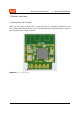
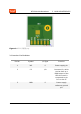
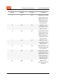

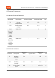
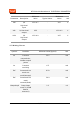
Table Of Contents

BT2S Module Datasheet 3 MODULE INTERFACES
Pin No. Symbol I/O Type Function
4 C3 I/O Common I/O, which
can be used as a
PWM output of the
LED drive and is
connected to pin
PC3 on the IC
5 B7 I/O UART_RX and is
connected to pin
PB7 on the IC
6 D2 I/O Common I/O, which
can be used as a
PWM output of the
LED drive and is
connected to pin
PD2 on the IC
7 B1 I/O UART_TX and is
connected to pin
PB1 on the IC
8 C4 I/O SAR ADC Input, and
is connected to pin
PC4 on the IC
9 B5 I/O Common I/O, which
can be used as a
PWM output of the
LED drive and is
connected to pin
PB5 on the IC
10 RST 1/O Reset,and is
connected to pin 25
on the IC
5 / 21