
Product Manual


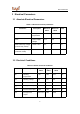

Table Of Contents

BT3L-A Datasheet
5
Figures
Figure 2-1 BT3L-A front and rear views............................................................................... 6
Figure 6-1 BT3L-A mechanical dimensions and rear solder pad dimensions.............13
Figure 6-2 HIC for BT3L-A................................................................................................... 14
Figure 6-3 Oven temperature curve................................................................................... 15
Tables
Table 2-1 BT3L-A interface pins............................................................................................ 6
Table 3-1 Absolute electrical parameters.............................................................................9
Table 3-2 Normal electrical conditions..................................................................................9
Table 3-3 Power consumption in different working modes............................................. 10
Table 4-1 Basic RF features.................................................................................................11
Table 4-2 Power during constant transmission................................................................. 11
Table 4-3 RX sensitivity.........................................................................................................12