CB2S Module Datasheet Hardware Product Development > Network Modules > Wi-Fi & BLE Dual Mode Module > CB Series Module Version: 20210408 Online Version
Contents Contents 1 Overview 1.1 Features . . . . . . . . . . . . . . . . . . . . . . . . . . . . . . . . . 1.2 Applications . . . . . . . . . . . . . . . . . . . . . . . . . . . . . . . 1.3 Change history . . . . . . . . . . . . . . . . . . . . . . . . . . . . . . 2 2 2 3 2 Module interfaces 2.1 Dimensions and package . . . . . . . . . . . . . . . . . . . . . . . . 2.2 Pin definition . . . . . . . . . . . . . . . . . . . . . . . . . . . . . . . 3 3 4 3 Electrical parameters 3.
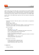
Contents CB2S is a low-power embedded Wi-Fi - Bluetooth module that Tuya has developed. It consistsof a highly integrated RF chip BK7231N and a few peripherals, and not only sup-ports the AP and STA dual-network-connection manner but supports the BluetoothLE network connection manner.
1 OVERVIEW 1 Overview CB2S is built-in with a 32-bit MCU with a running speed of up to 120 MHz, 2Mbyte flash, and 256-KB RAM, so as to support the Tuya IoT cloud connection. The MCU’s specially extended instructions for processing signals can effectively implement audio encoding and decoding. Besides, it has rich peripherals, such as PWM, UART, and SPI. The six 32-bit PWM output makes the chip very suitable for high-quality LED control. 1.
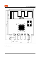
2 • • • • • • MODULE INTERFACES Smart household and home appliances Smart socket and light Industrial wireless control Baby monitor Network camera Intelligent bus 1.3 Change history Version after update Update date Updated content 04/06/2021 This is the first release. V1.0.0 04/06/2021 Updated test data V1.0.1 2 Module interfaces 2.1 Dimensions and package The CB2S dimensions are 17.9±0.35 mm (L)×14.9±0.35 mm (W) ×2.8±0.1 mm (H).
2 2.
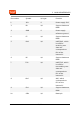
2 MODULE INTERFACES Pin number Symbol I/O type Function 1 3V3 P Power supply 3V3 2 P8 I/O Support hardware PWM 3 GND P Power supply reference ground 4 P7 I/O Support hardware PWM 5 RX1 I/O UART_RX1, which is used for receiving user data and corresponds to P10 of the internal IC 6 P6 I/O Support hardware PWM 7 TX1 I/O UART_TX1, which is used for transmitting user data and corresponds to P11 of the internal IC 8 ADC I/O ADC, which corresponds to P23 on the internal IC 9
2 MODULE INTERFACES Pin number Symbol I/O type Function 11 P26 I/O Support hardware PWMC Test point RX2 I/O UART_RX2, which corresponds to P1 on the internal IC, prohibition of use this pin Test point TX2 I/O UART_TX2, which is used for outputting logs and corresponds to P0 of the internal IC Test point CSN I/O Mode selection pin. If connected to the ground before powered on, enter the firmware test mode.
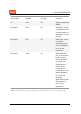
3 ELECTRICAL PARAMETERS 3 Electrical parameters 3.1 Absolute electrical parameters Minimum value Maximum value Unit Parameter Description Ts Storage temperature -55 125 ℃ VBAT Power supply voltage -0.3 3.9 V Static electricity discharge voltage (human body model) TAMB-25℃ -4 4 KV Static electricity discharge voltage (machine model) TAMB-25℃ -200 200 V 3.2 Normal working conditions Minimum value Parameter Description Ta Working temperature -40 VBAT Power supply voltage 3.
3 ELECTRICAL PARAMETERS Minimum value Typical value Maximum value Unit Parameter Description VOL I/O low level output VSS - VSS+0.3 V VOH I/O high level output VBAT-0. 3 - VBAT V Imax I/O drive current - 6 20 mA 3.
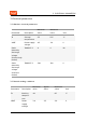
4 Working mode Working status, Ta = 25°C RF PARAMETERS Average value Maximum value (Typical value) Unit Quick network connection state (Bluetooth ) The module is in the fast network connection state and the Wi-Fi indicator flashes fast 63 245 mA Quick network connection state (AP) The module is in the hotspot network connection state and the Wi-Fi indicator flashes slowly 80 270 mA Quick network connection state (EZ) The module is in the fast network connection state and the Wi-Fi indicator
4 RF PARAMETERS Parameter Description Working frequency 2.412 to 2.480 GHz Wi-Fi standard IEEE 802.11 b/g/n (channels 1 to 14) Data transmission rate 11b: 1, 2, 5.5, 11 (Mbps); 11g: 6, 9, 12, 18, 24, 36, 48, 54 (Mbps); 11n: HT20 MCS0~7; 11n: HT40 MCS 0 to 7 Antenna type PCB 4.2 Wi-Fi transmission performance Typical value Maximum value Unit Average RF output power, 802.11b CCK Mode 11M 16 - dBm Average RF output power, 802.11g OFDM Mode 54M 15 - dBm Average RF output power, 802.
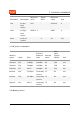
4 RF PARAMETERS 4.3 Wi-Fi receiving performance Typical value Maximum value Unit - -88 - dBm PER<10%, RX sensitivity, 802.11g OFDM Mode 54M -74 - dBm PER<10%, RX sensitivity, 802.11n OFDM Mode MCS7 -73 - dBm PER<10%, RX sensitivity, Bluetooth LE 1M -96 - dBm Unit Parameter PER<8%, RX sensitivity, 802.11b DSSS Mode 11M Minimum value 4.
5 Parameter Frequency error Minimum value -150 ANTENNA INFORMATION Typical value Maximum value Unit - 150 kHz Unit 4.5 Bluetooth LE receiving performance Parameter Minimum value Typical value Maximum value RX sensitivity - -96 - dBm Maximum RF signal input -10 - - dBm Intermodulation - - -23 dBm Co-channel suppression ratio - 10 - dB 5 Antenna information 5.1 Antenna type The CB2S select the PCB antenna. 5.
6 PACKAGING INFORMATION AND PRODUCTION INSTRUCTIONS 6 Packaging information and production instructions 6.
6 PACKAGING INFORMATION AND PRODUCTION INSTRUCTIONS 14 / 22
6 PACKAGING INFORMATION AND PRODUCTION INSTRUCTIONS 6.2 Production instructions • For the in-line module developed by Tuya, the wave soldering equipment is most preferred and manual soldering is less preferred. After being unpacked, the module must be soldered within 24 hours. Otherwise, it must be put into the drying cupboard where the RH is not greater than 10%, or it needs to be packaged under vacuum again and record the exposure time (the total exposure time cannot exceed 168 hours).
6 PACKAGING INFORMATION AND PRODUCTION INSTRUCTIONS – Tin bar, tin wire, and flux – Oven temperature tester • Baking equipment: – Cabinet oven – Anti-static heat-resistant pallets – Anti-static heat-resistant gloves • The module needs to be baked in the following cases: – The vacuum packing bag was found to be damaged before being unpacked. – There is no humidity indicator card (HIC) in the vacuum packing bag. – After being unpacked, 10% and above circles on the HIC become pink.
6 PACKAGING INFORMATION AND PRODUCTION INSTRUCTIONS – The amount of soldering flux. – The height of the wave peak. – Whether the tin slag and copper content in the wave soldering tank exceed standards. – Whether the window and thickness of the wave soldering fixture are appropriate. – Whether the wave soldering oven temperature curve is reasonable. 6.3 Recommended oven temperature curve and temperature For oven temperature setting, refer to oven temperatures for wave soldering.
6 PACKAGING INFORMATION AND PRODUCTION INSTRUCTIONS Recommended wave soldering oven temperature Recommended manual soldering temperature Preheat temperature 80 to 130 °C Soldering temperature 360±20°C Preheat time 75 to 100s Soldering time < 3s/point Peak contact time 3 to 5s NA NA Temperature of tin cylinder 260±5°C NA NA Ramp-up slope ≤2°C/s NA NA Ramp-down slope ≤6°C/s NA NA 6.
6 PACKAGING INFORMATION AND PRODUCTION INSTRUCTIONS 19 / 22
8 APPENDIX: STATEMENT 7 MOQ and packaging information Product number MOQ (pcs) Shipping packaging method CB2S 3600 Tape reel The number of modules per reel The number of reels per carton 900 4 8 Appendix: Statement FCC Caution: Any changes or modifications not expressly approved by the party responsible for compliance could void the user’s authority to operate this device. This device complies with Part 15 of the FCC Rules.
8 APPENDIX: STATEMENT rolled environment. This device should be installed and operated with a minimum distance of 20cm between the radiator and your body. Important Note This radio module must not be installed to co-locate and operating simultaneously with other radios in the host system except following FCC multi-transmitter product procedures. Additional testing and device authorization may be required to operate simultaneously with other radios.
8 APPENDIX: STATEMENT of Directive 2014/53/EU,2011/65/EU. A copy of the Declaration of conformity can be found at https://www.tuya.com. This product must not be disposed of as normal household waste, in accordance with the EU directive for waste electrical and electronic equipment (WEEE-2012/19/EU). Instead, it should be disposed of by returning it to the point of sale, or to a municipal recycling collection point. The device could be used with a separation distance of 20cm to the human body.