CR2S Module Datasheet Hardware Product Development > Network Modules > Wi-Fi & BLE Dual Mode Module > CR Series Module Version: 20210304 Online Version
Contents Contents 1 Overview 1.1 Features . . . . . . . . . . . . . . . . . . . . . . . . . . . . . . . . . 1.2 Applications . . . . . . . . . . . . . . . . . . . . . . . . . . . . . . . 1.3 Change history . . . . . . . . . . . . . . . . . . . . . . . . . . . . . . 2 2 2 3 2 Module interfaces 2.1 Dimensions and package . . . . . . . . . . . . . . . . . . . . . . . . 2.2 Pin definition . . . . . . . . . . . . . . . . . . . . . . . . . . . . . . . 3 3 4 3 Electrical parameters 3.
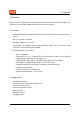
Contents CR2S is a low-power embedded Wi-Fi+BLE module that Tuya has developed. Embedded with the Wi-Fi network protocol stack and rich library functions, it consists of a highly integrated RF chip (RTL8720CM). With the maximum CPU clock rate of 100 MHz, CR2S also contains a low-power Real-M300 (KM4) microcontroller unit (MCU), a WLAN MAC, a 1T1R WLAN, a 4-MB pseudo-static random-access memory (PSRAM), 4-MB flash memory, and rich extensive peripherals.
1 OVERVIEW 1 Overview CR2S is an RTOS platform that integrates all function libraries of the Wi-Fi MAC and TCP/IP. You can develop embedded Wi-Fi products as required. 1.1 Features • Embedded low-power KM4 MCU, which can also function as an application processor Main clock rate: 100 MHz • Working voltage: 3.0 to 3.6 V • Peripherals: 6 (general-purpose input/output) GPIOs and 1 universal asynchronous receiver/transmitter (UART) • Wi-Fi/Bluetooth connectivity – – – – – – – – – 802.
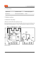
2 MODULE INTERFACES 1.3 Change history Update date Updated content Version after update 2021-01-28 This is the first release. V1.0.0 2 Module interfaces 2.1 Dimensions and package CR2S has 2 rows of pins with a spacing of 2 mm. The CR2S dimensions are 15±0.35 mm (W)×18±0.35 mm (L)× 4.45±0.15 mm (H). The height of the back panel is 1.55 mm.
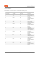
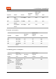
2 MODULE INTERFACES 2.2 Pin definition The definition of interface pins is shown in the following table: Pin number Symbol I/O Type Function 1 3V3 P Power supply pin (3.
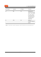
2 MODULE INTERFACES Pin number Symbol I/O Type Function 10 EN I/O Enabling pin, active at the high level. The module has been pulled to the high level and the user can control the pin externally 11 PA2 I/O GPIOA_2, hardware PWM, IC Pin 18 Note: P indicates a power supply pin and I/O indicates an input/output pin.
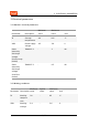
3 ELECTRICAL PARAMETERS 3 Electrical parameters 3.1 Absolute electrical parameters Minimum value Maximum value Unit Parameter Description Ts Storage temperature -40 105 ℃ VDD Power supply voltage -0.3 3.6 V Static electricity discharge voltage (human body model) TAMB-25℃ - 2 KV Static electricity discharge voltage (machine model) TAMB-25℃ - 0.5 KV 3.
3 ELECTRICAL PARAMETERS Minimum Parameter Description value Typical value Maximum value Unit VIL I/O low level input - - 0.8 V VIH I/O high level input 2.0 - - V VOL I/O low level output - - 0.4 VOH I/O high level output 2.4 - - Imax I/O drive current - - 16 mA Cpad Input pin capacitance - 2 - pF V V 3.
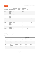
3 ELECTRICAL PARAMETERS Peak value (Typical value) Unit Symbol Mode Power Average value IRF 11g 54Mbps 17.5 dBm 173 259 mA IRF 11n BW20 MCS7 13 dBm 143 203 mA IRF 11n BW20 MCS7 16.5 dBm 165 244 mA RX power consumption: Peak Value (Typical Value) Unit Symbol Mode Average Value IRF 11B 11M 62 67 mA IRF 11G 54M 61 68 mA IRF 11N HT20 MCS7 62 69 mA Average value Peak value (Typical value) Unit 77 331 mA 3.
4 Working mode Working status, TA = 25°C RF PARAMETERS Average value Peak value (Typical value) Unit Idle state The module is connected to the network and the Wi-Fi indicator is always on 68 321 mA Network connection operation state The module is connected to the network and the Wi-Fi indicator is always on 67 316 mA Disconnected state The module is disconnected and the Wi-Fi indicator is dark 67 312 mA 4 RF parameters 4.1 Basic RF features Parameter Description Frequency range 2.
4 RF PARAMETERS Parameter Description Data transmission rate 11n: HT20 MCS0 to 7 Antenna type PCB antenna with a peak gain of 1.7 dBi 4.2 TX performance TX performance Typical value Maximum value Unit Average RF output power, 802.11b CCK Mode 1M 17.5 - dBm Average RF output power, 802.11g OFDM Mode 54M 14.5 - dBm Average RF output power, 802.11n OFDM Mode MCS7 13.5 - dBm Average RF output power, BLE 4.2 1M 6.
4 Typical value Maximum value Unit EVM@802.11b CCK 11 Mbps Mode 17.5 dBm - -10 dB EVM@802.11g OFDM 54 Mbps Mode 14.5 dBm - -29 dB EVM@802.11n OFDM MCS7 Mode 13.5 dBm - -30 dB Minimum Value Typical Value Maximum Value Unit - -97 - dBm Parameter Minimum value RF PARAMETERS RX Performance Parameter PER<8%, RX sensitivity, 802.11b CCK Mode 1M PER<10%, RX sensitivity, 802.11g OFDM Mode 54M -75 - dBm PER<10%, RX sensitivity, 802.
4 Parameter Minimum Value PER<10%, RX sensitivity, BLE 4.
5 ANTENNA INFORMATION 5 Antenna information 5.1 Antenna type CR2S uses only an onboard PCB antenna with a peak gain of 1.7 dBi. 5.2 Antenna interference reduction To ensure the optimal Wi-Fi performance when the Wi-Fi module uses an onboard PCB antenna, it is recommended that the antenna be at least 15 mm away from other metal parts.
6 PACKAGING INFORMATION AND PRODUCTION INSTRUCTIONS 6 Packaging information and production instructions 6.1 Mechanical dimensions The mechanical dimensions of the PCB of CR2S are 15±0.35 mm (W)×18±0.35 mm (L) ×0.8±0.1 mm (H). The following figure shows the mechanical dimensions of CR2S: {width=300px} Note: The default dimensional tolerance is ±0.35 mm. If you have specific requirements on dimensions, make them clear in the module datasheet after communication. 6.
6 PACKAGING INFORMATION AND PRODUCTION INSTRUCTIONS The following is the diagram of the packaging of the PCB of CR2S: 6.3 Production instructions 1. For the in-line module developed by Tuya, wave soldering equipment is most preferred and manual soldering is less preferred. After being unpacked, the module must be soldered within 24 hours; otherwise, it needs to be packaged again under vacuum. 2.
6 PACKAGING INFORMATION AND PRODUCTION INSTRUCTIONS – Tin bar, tin wire, and flux – Oven temperature tester • Baking equipment: – Cabinet oven – Anti-static heat-resistant trays – Anti-static heat-resistant gloves 3. The module developed by Tuya needs to be baked in the following cases: • • • • • Vacuum packaging bag was damaged before unpacking. There is no humidity indicator card (HIC) in the vacuum packaging bag. After unpacking, 30% and above circles on the HIC become pink.
6 PACKAGING INFORMATION AND PRODUCTION INSTRUCTIONS 6.4 Recommended oven temperature curve and temperature For oven temperature setting, refer to oven temperatures for wave soldering. The peak temperature is 260℃±5℃.
6 PACKAGING INFORMATION AND PRODUCTION INSTRUCTIONS 360℃±20℃ Pre-heat time 75 to 100s Soldering time <3s/point Peak contact time 3 to 5s NA NA Temperature of tin tank 260±5℃ NA NA Ramp-up slope ≤2℃/s NA NA Cooling slope ≤6℃/s NA NA 6.5 Storage conditions Storage conditions for a delivered module are as follows: • The moisture-proof bag is placed in an environment where the temperature is less than 30°C and the relative humidity is less than 70%.
6 PACKAGING INFORMATION AND PRODUCTION INSTRUCTIONS • The package contains a humidity indicator card (HIC).
8 APPENDIX: STATEMENT 7 MOQ and packaging information Product number MOQ (pcs) Shipping packaging method CR2S 4400 Tape reel The number of modules per reel The number of reels per carton 1100 4 8 Appendix: Statement FCC Caution: Any changes or modifications not expressly approved by the party responsible for compliance could void the user’s authority to operate this device. This device complies with Part 15 of the FCC Rules.
8 APPENDIX: STATEMENT rolled environment. This device should be installed and operated with a minimum distance of 20cm between the radiator and your body. Important Note This radio module must not be installed to co-locate and operating simultaneously with other radios in the host system except following FCC multi-transmitter product procedures. Additional testing and device authorization may be required to operate simultaneously with other radios.
8 APPENDIX: STATEMENT of Directive 2014/53/EU,2011/65/EU. A copy of the Declaration of conformity can be found at https://www.tuya.com. This product must not be disposed of as normal household waste, in accordance with the EU directive for waste electrical and electronic equipment (WEEE-2012/19/EU). Instead, it should be disposed of by returning it to the point of sale, or to a municipal recycling collection point. The device could be used with a separation distance of 20cm to the human body.