HEWRQU1 Module Datasheet Version: 20220214 Online Version
Contents Contents 1 Product overview 1.1 Features . . . . . . . . . . . . . . . . . . . . . . . . . . . . . . . . . 1.2 Applications . . . . . . . . . . . . . . . . . . . . . . . . . . . . . . . 1.3 Change history . . . . . . . . . . . . . . . . . . . . . . . . . . . . . . 2 2 2 3 2 Module interfaces 2.1 Dimensions and footprint . . . . . . . . . . . . . . . . . . . . . . . . 2.2 Pin definition . . . . . . . . . . . . . . . . . . . . . . . . . . . . . . . 2.3 Definitions on test pins . . . . . . . . . .
Contents Developed by Tuya, HEWRQU1 is a Wi-Fi module that is suitable for serial communication in which the level is changed from 5V TTL to 3.3V TTL. It consists of a highly integrated wireless RF chip (RTL 8710BN), an extension chip, and a DC-DC chip. Besides, it has a Wi-Fi network protocol stack and rich library functions inside. It further contains a low-power ARM CM4FCPU, a 2-MB flash memory, and a 256-KB SRAM.
1 Product overview 1 Product overview HEWRQU1 is an RTOS platform that integrates all function libraries of the Wi-Fi MAC and TCP/IP. On the basis of serial communication, you can develop embedded Wi-Fi products as required. 1.1 Features • • • • • Low-power CPU, which can also function as an application processor The maximum clock rate: 125 MHz Operating voltage: 4.5 to 5.5V Peripheral: 1 UART Wi-Fi connectivity – – – – – – 802.11 b/g/ n_HT20 HT40 Channels 1 to 14@2.
1 Product overview • Baby monitor • Network camera • Intelligent bus 1.3 Change history Update date Updated content Version after update Sep. 29, 2021 This is the first release. V1.0.
2 Module interfaces 2 Module interfaces 2.1 Dimensions and footprint The dimensions of HEWRQU1 are 42.75±0.35 mm (L)×21.7±0.35 mm (W) ×4.5±0.15 mm (H).
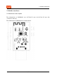
2 Module interfaces 2.
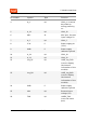
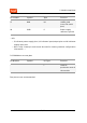
2 Module interfaces Pin number Symbol Type Function 4 A_0 I/O GPIO_0. It cannot be pulled up during powering on. 5 A_12 I/O GPIO_12 6 ADC AI ADC port, the max input voltage 5V 7 A_5 I/O GPIO_5 8 3.3V P Power supply pin (3.
2 Module interfaces Pin number Symbol Type Function 17 RXD I/O UART0_RXD (user-side serial port) 18 GND P Power supply reference ground :::info • P indicates power supply pins, I/O indicates input/output pins and AI indicates analog input pins. • RST is only a reset pin and cannot be used for clearing network configuration information. ::: 2.3 Definitions on test pins Pin Number Symbol - I/O Type Function I Used for production tests of the module Test pins are not recommended.
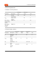
3 Electrical parameters 3 Electrical parameters 3.1 Absolute electrical parameters Minimum value Maximum value Unit Parameter Description Ts Storage temperature -40 125 ℃ VBAT Power supply voltage - 5.5 V ESD voltage (human body model) TAMB-25℃ - 2 KV ESD voltage (machine model) TAMB-25℃ - 0.5 KV 3.2 Normal working conditions Minimum value Typical value Maximum value Unit Parameter Description Ta Operating temperature -20 - 85 ℃ VBAT Power supply voltage 4.5 5 5.
3 Electrical parameters Minimum value Typical value Maximum value Unit Parameter Description VOL Low voltage output - - VCC*0.1 V VOH High voltage output VCC*0.8 - VCC V Imax IO drive current - - 16 mA Typical Value Unit 3.3 TX and RX power consumption Working Status Mode Rate Transmit Power/Receive Transmit 11 b 11Mbps +17dBm 285 mA Transmit 11g 54Mbps +14.5dBm 255 mA Transmit 11n-HT20 MCS7 +13.5dBm 235 mA Transmit 11n-HT40 MCS7 +13.
3 Electrical parameters Operating mode Operating status, Ta = 25°C Average value Maximum value (Typical value) Unit Quick pairing The module is in fast pairing state 88 150 mA Hotspot The module is in pairing state through the hotspot and the Wi-Fi indicator always flashes slowly 95 245 mA Connected The module is connected to the network and the Wi-Fi indicator is always on 55 220 mA The above parameters may vary with firmware functions.
4 RF parameters 4 RF parameters 4.1 Basic RF features Parameter Description Operating frequency 2.412 to 2.483.5 GHz Wi-Fi standard IEEE 802.11 b/g/n (channels 1 to 14) Data transmission rate 11b: 1, 2, 5.5, and 11 (Mbps); 11g: 6, 9, 12, 18, 24, 36, 48, and 54 (Mbps); 11n: HT20 MCS 0 to 7; HT40 MCS 0 to 7 Antenna type PCB antenna 4.2 TX performance TX performance Minimum value Typical value Maximum value Unit Average RF output power, 802.
4 RF parameters Typical value Maximum value Unit - 20 ppm Minimum value Typical value Maximum value Unit PER<8%, RX sensitivity, 802.11b DSSS Mode 11M - -90 - dBm PER<10%, RX sensitivity, 802.11a OFDM Mode 54M - -73 - dBm PER<10%, RX sensitivity, 802.11n OFDM Mode HT20-MCS7 - -70 - dBm Parameter Frequency error Minimum value -20 4.
5 Antenna 5 Antenna 5.1 Antenna type HEWRQU1 supports two types of antennas: Onboard PCB antenna and external antenna. By default, the onboard PCB antenna is preferred. 5.2 Interference reduction To ensure optimal Wi-Fi performance when the Wi-Fi module uses a PCB antenna, it is recommended that the antenna be at least 15 mm away from other metal parts. To prevent adverse impact on the radiation performance, avoid copper or traces within the antenna area of the PCB. During layout, you should note: 1.
5 Antenna 5.3 Specifications of antenna connector There is no connector for the antenna currently.
6 Packaging information and production instructions 6 Packaging information and production instructions 6.1 Mechanical dimensions 6.2 Production instructions Storage conditions for a delivered module are as follows: • The moisture-proof bag must be placed in an environment where the temperature is below 30°C and the relative humidity is lower than 70%. • The shelf life of a dry-packaged product is 6 months from the date when the product is packaged and sealed.
6 Packaging information and production instructions 6.3 Recommended oven temperature curve We mount the PCB with the SMT according to the following temperature curve. The peak temperature is 245°C. Refer to IPC/JEDEC standard. Peak Temperature: <245℃. Number of Times: ≤2.
6 Packaging information and production instructions 6.4 Storage conditions Specifications of terminal This module adopts the USB2.0 180° sinking-plate straight-leg plug connector.
6 Packaging information and production instructions Product model MOQ (pcs) HEWRQU1 400 Packing method Honeycomb carton 18 / 22 The number of modules per reel The number of reels per carton 200 2
7 Appendix: Statement 7 Appendix: Statement FCC Caution: Any changes or modifications not expressly approved by the party responsible for compliance could void the user’s authority to operate this equipment.The module is limited to installation in mobile or fixed applications. This device complies with Part 15 of the FCC Rules.
7 Appendix: Statement The host product manufacturer is responsible for compliance to any other FCC rules that apply to the host not covered by the modular transmitter grant of certification. The final host product still requires Part 15 Subpart B compliance testing with the modular transmitter installed.The separate approval is required for all other operating configurations including portable configurations with respect to Part 2.1093 and different antenna configuration.
7 Appendix: Statement Radiation Exposure Statement This equipment complies with IC radiation exposure limits set forth for an uncontrolled environment. This equipment should be installed and operated with minimum distance 20 cm between the radiator & your body. Déclaration d'exposition aux radiations: Cet équipement est conforme aux limites d'exposition aux rayonnements ISED établies pour un environnement non contrôlé.
7 Appendix: Statement circonstances, l'intégrateur OEM sera chargé de réévaluer le produit final (y compris l'émetteur)et l'obtention d'une autorisation distincte au Canada. End Product Labeling This transmitter module is authorized only for use in device where the antenna may be installed such that 20 cm may be maintained between the antenna and users. The final end product must be labeled in a visible area with the following: “Contains IC:23243-HEWRQU1”.