
Product Manual


WB2S Datasheet
6
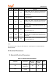
2 Module Interfaces
2.1 Dimensions and Footprint
WB2S has two rows of pins with a 2 mm pin spacing.
The WB2S dimensions (H x W x D) are 3.3 mm x 15 mm x 18 mm. Figure 2-1 shows the
WB2S front and rear views.
Figure 2-1 WB2S front and rear views
Note:
The default dimensional tolerance is ±0.35 mm, and the tolerance for some
measurements is ±0.1 mm. The PCB thickness is 1.0±0.1 mm.
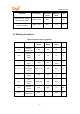
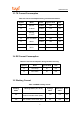
2.2 Interface Pin Definition
Table 2-1 WB2S interface pins
Pin No.
Symbol
I/O Type Function
1 VBAT P
Power supply pin (3.3 V), which is connected to
the VBAT pin on the internal IC
2 PWM2 I/O
Common GPIO, which is connected to the P8 pin
on the internal IC
3 GND P Power supply reference ground pin
4 PWM1 I/O
Common GPIO, which is connected to the P7 pin
on the internal IC