
Product Manual

WB2S Datasheet
7
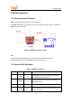
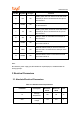
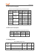
Pin No.
Symbol
I/O Type Function
5 RX I/O
UART1_RXD, which is used as a user-side serial
interface pin and is connected to the P10 pin on
the internal IC
6 PWM0 I/O
Common GPIO, which is connected to the P6 pin
on the internal IC
7 TX I/O
UART1_TXD, which is used as a user-side serial
interface pin and is connected to the P11 pin on
the internal IC
8 AD AI
ADC pin, which is connected to the P23 pin on
the internal IC
9 PWM4 I/O
Common GPIO, which is connected to the P24
pin on the internal IC
10 CEN I/O
External enabled reset pin, which is active at a
low level and is connected to the CEN pin on the
internal IC
11 PWM5 I/O
Common GPIO, which is connected to the P26
pin on the internal IC
Note:
P indicates a power supply pin, I/O indicates an input/output pin, and AI indicates an
analog input pin.
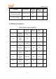
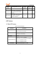
3 Electrical Parameters
3.1 Absolute Electrical Parameters
Table 3-1 Absolute electrical parameters
Parameter Description Minimum
Value
Maximum
Value
Unit
Ts
Storage
temperature
–20 85 °C
VCC
Power supply
voltage
–0.3 3.6 V