Instruction Manual BL1.5 - BL3 - BL5 BL7 - BL10 BL15 - BL20 BL7913 - BL7914 Dosing Pumps These Pumps are in Compliance with the CE Directives http://www.hannainst.
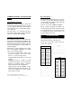
Dear Customer, Thank you for choosing a Hanna product. Please read this instruction manual carefully before using the pump. This manual will provide you with the necessary information for a correct use of the pump, as well as a precise idea of its versatility. If you need more technical information, do not hesitate to e-mail us at tech@hannainst.com. These instruments are in compliance with directives EN 50081-1 and EN 50082-1. TABLE OF CONTENTS Preliminary Examination ............................
Always store chemicals in safe, out of reach places. Follow the directions for use with each chemical. Do not assume chemicals are the same because they look alike. Hanna Instruments cannot be held responsible for the misuse of chemicals or the pump. Always wear protective clothing (gloves and safety glasses) when working near chemical dosing pumps. When pumping chemicals, make sure all tubes are securely attached to the fittings.
BL7913 IPS VARIABLE FLOW RATE PUMP BL7914 IPS MULTIRANGE PUMP BL 7913 is a single range dosing pump, ideal for use when the pumping requirement is constant. The individual pump flow rates can also be adjusted on the front panel from 0 to 100%. Four models are available with different dosing capacities: BL7914 offers four different ranges providing greater flexibility. BL7913/2 5.4 lph (1.4 gph) @ 0.5 bar (7.4 psi) BL7913/5 7.6 lph (2.0 gph) @ 0.5 bar (7.4 psi) BL7913/10 10.0 lph (2.6 gph) @ 0.
COMMON FEATURES OF BLACKSTONE PUMPS High quality materials BlackStone pumps incorporate Kynar® and Teflon® into their diaphragms, hose connectors and pump heads to provide maximum protection for parts in contact with aggressive chemicals. The ball valves are constructed in glass. The body is made of fiber-reinforced polypropylene for strength and durability.
BL20 BL5 bar (psi) 0.5 (7.4) 1 (14.7) 2 (29.4) 3 (44.1) 4 (58.8) 5 (73.5) 6 (88.2) 7 (102.9) 8 (117.6) 9 (132.3) 10 (147) bar (psi) 0.5 (7.4) 1 (14.7) 2 (29.4) lph (gph) 15.8 (4.18) 12.2 (3.23) 10.8 (2.86) 9.3 (2.46) 7.9 (2.09) 6.5 (1.72) 5.8 (1.53) 5.0 (1.32) 4.3 (1.14) 4.0 (1.06) 3.6 (0.95) lph (gph) 18.3 (4.84) 15.2 (4.02) 13.6 (3.60) BL7913 bar (psi) 0.5 (7.4) 1.0 (14.7) 2.0 (29.4) 4.0 (58.8) 6.0 (88.2) BL7913/2 lph (gph) 5.4 (1.40) 4.6 (1.20) 4.1 (1.07) 3.2 (0.83) 2.1 (0.
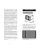
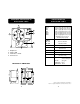
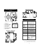
SPECIFICATIONS OF BLACKSTONE PUMPS FUNCTIONAL DESCRIPTION OF BLACKSTONE PUMPS 2 STROKE 50 40 60 70 30 80 20 1 3 90 10 0 100 FLOW RATE % MODEL: BL3-12 OUTPUT: 3L/H 12 BAR 4 1. 2. 3. 4. Pumphead Stroke LED Flow Rate % Knob Power Cord FLOW RATE BL1.5 BL3 BL 5 BL7 BL10 BL15 BL20 1.5 lph (0.4 gph) @13 bar (188.5 psi) 2.9 lph (0.8 gph) @ 8 bar (116 psi) 5.0 lph (1.3 gph) @ 7 bar (101.5 psi) 7.6 lph (2.0 gph) @ 3 bar (43.5 psi) 10.8 lph (2.9 gph) @ 3 bar (43.5 psi) 15.2 lph (4.
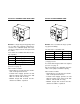
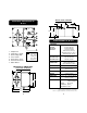
Bottom View of BL7913 FUNCTIONAL DESCRIPTION OF BL 7913 110 mm 4.33" 55 mm 2.16" 17 mm 0.67" 129 mm 5.08" 142 mm 5.60" 99 mm 3.90" 5 mm 0.19" SPECIFICATIONS OF BL 7913 FLOW RATE BL7913/2 BL7913/5 BL 7913/10 BL7913/15 1. 2. 3. 4. 5. 6. 7. Pumphead Flow Rate % Knob Overheating LED Fuse Holder Connections Cover Power Connections Cable Gland. Unplug the instrument from power supply before replacing the fuse.
Bottom View of BL7914 FUNCTIONAL DESCRIPTION OF BL 7914 110 mm 4.33" 55 mm 2.16" 17 mm 0.67" 129 mm 5.08" 142 mm 5.60" 99 mm 3.90" 5 mm 0.19" SPECIFICATIONS OF BL 7914 FLOW RATE 1. 2. 3. 4. 5. 6. 7. 8. Pumphead Flow Rate % Knob Overheating LED Capacity Knob Fuse Holder Connections Cover Power Connections Cable Gland. Unplug the instrument from power supply before replacing the fuse.
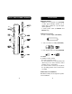
VALVE / HOSE ASSEMBLY DIAGRAM INSTALLATION Materials Needed • LDPE hose (7 meter/22 feet) (included) or other type of tubings (Teflon®, for example) more suitable for a specific application (optional) • a 3-wire power cable (for BL7913 and BL7914 only) NECK Optional Accessories • 4 each, ceramic weights (HI 720032) • 1 each, foot valve assembly (HI 712005) • 1 each, injection valve assembly (HI 721004) Location A suitable location should: • be near to a power source • be conveniently close to the inj
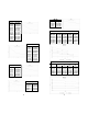
The pump can be mounted directly on a wall or tank (see pages 12-17 for the specific mounting dimensions). Power Requirements BlackStone pumps are designed to operate to specifications within the following voltage ranges: 100 - 130 Volts for 115V models 200 - 240 Volts for 220V models To ensure maximum performance, check the voltage at the point of supply to verify that it is sufficient. It is recommended that you install a 1 Amp circuit breaker between the pump and the power supply.
Color coding for wires: Blue - Live Brown - Neutral Yellow/Green - Ground (earth) • Remove the protective plastic plate covering the terminals by removing the 2 screws on both sides of the plate. Black Stone BL 50 40 60 7914 70 30 80 20 90 10 0 100 FLOW % 5 OVERHEATING 10 2 IP 54 WITH TRANSPARENT COVER INSTALLED 15 LITRES/HOUR BLUE 0 110 220 115 240 BROWN YELLOW/ GREEN It is recommended that the system be connected to a power line/leg equipped with a circuit breaker of 1 Amp.
terminals. • Slide the fitting up, screw it onto the base and tighten the nut to form the watertight seal. • Replace the protective plastic cover. • Replace the transparent cover and gasket seal on the front panel. Permanent Connection using 3/8"PVC pipe UNION CONNECTION All piping for the ADAPTER pump feed and disDISCHARGE VALVE charge should be PUMP plumbed to the loSUCTION VALVE cation of the pump.
• Repeat the same installation procedure for the hose connections on the discharge end with the injection assembly (HI721004). Assembling the Hose to the Valve The end of the valve is specially tapered to form a leak free seal when the hose is properly installed. Be sure to seat the hose completely so that there is no gap. Push the hose until it covers the end of the valve completely.
EXAMPLE OF TYPICAL INSTALLATIONS HOSE PIPE PUMP CONNECTION FILTER / FOOT VALVE RESEVOIR CHECK VALVE MANUAL SHUTOFF VALVE LEGEND Flooded Suction Installation Suggested Installation for consistent output when using a low stroke rate. Also suggested for highly viscous chemicals. A slight suction pressure avoids self-priming problems, especially with high viscosity liquids.
For BlackStone Pumps An LED indicator will light up each time a stroke begins. OPERATIONAL GUIDE STARTUP At startup, purge all chemical gases and air from the suction tubing, valves and pump head. Start the pump. When all the air or gas is vented, the solution being metered will appear in the output line.
Actual Flow Rate The actual flow rate depends upon the operating pressure which includes resistance at the injection fittings, hose and piping, the chemical viscosity and suction lift. The Flow Rate Control adjusts the flow up to 100% of the rated output. Less back pressure will increase the output, more will decrease it. To determine the correct setting for your application, use the following procedure. 1. Be sure that the pump is primed and that the output connections are completed at the injection point.
TROUBLESHOOTING GUIDE Electrical The pump does not operate when turned ON: • Check the power supply and connections. Voltage should be between 100 - 130 VAC for 115 V models and between 200 240 VAC for 220 V models. • Check wiring color scheme. See Installation section on page 19 or call for technical assistance. • Check fuse (BL7913 and BL7914). Liquid • Check for any changes in the viscosity of the chemicals being used.
MAINTENANCE Your BlackStone Pump is designed to give you years of trouble-free service. Maintenance should be the preventative type, that is, periodic cleaning and inspecting for any damage or leakage. Cleaning the Suction, Discharge and Injection Valves Remove the valves from the pumphead, the injection fitting and the feed. Keep the suction and discharge valves separated as they are not interchangeable. Disassemble each valve and clean it with a neutral liquid. Inspect the Kynar® springs.
CHEMICAL COMPATIBILITY GUIDE Partial Listing of Chemicals that can be used with BlackStone Pumps (Rated for 45°C.
ACCESSORIES SPARE PARTS HI 721102 Discharge Valve (Glass Ball, Valve O-Ring, Hose Connector) HI 721008 4 x Ceramic Weights HI 721101 Pumphead, O-Ring, 6 screws and washers (for BL7, BL10, BL15, BL20, BL7913 and BL7914) Pumphead Large Teflon® Diaphragm Aluminum Piston Aluminum Disk HI 721106 TUBE NUT HEAD NIPPLE HI 721103 VITON® O-RING CHECK SP ACER VALVE VITON® BALL SEAT O-RING Suction Valve (Glass Ball, Valve O-Ring, Hose Connector) CHECK VALVE BALL SEAT HI 721003 HI 721004 HEAD NIPPLE TUBE
WARRANTY All Hanna Instruments pumps are warranted for one year against defects in workmanship and materials when used for their intended purpose and maintained according to instructions. This warranty is limited to repair or replacement free of charge. Damages due to accident, misuse, tampering or lack of prescribed maintenance are not covered. If service is required, contact the dealer from whom you purchased the instrument.
h t t p : / / w w w . h a n n a i n s t .