
User Guide
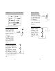


2120
• The ambient temperature of the pump,
when in operation, should be between 0
and 50°C (32 to 122°F) and should be
protected from direct exposure to outdoor
elements (direct sunlight, rain, extreme
temperatures, high humidity, etc.).
• Generally speaking, the shorter the suc-
tion distance, the more efficient the pump
operates.
• The pump should be placed in a conven-
tional location that will allow easy access
to the control and connections. It should
be placed so that regular visual inspec-
tions of the connections and hoses are
facilitated.
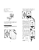
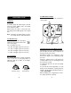
Vertical Surface Mounting
Once you have selected the best installation
site, simply screw or bolt the unit into a wall
or mounting panel above the chemical feed
tank.
The 4 mounting screw holes on the pump
will accommodate up to a 5mm (3/16") screw
or bolt (remember to use heavy screws or
bolts to secure the system).
Be sure you do not over tighten and cause
excessive stress on the mounting holes.
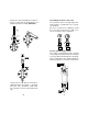
For BL7913 and BL7914
Make sure to leave a slight overhang in
front to allow for the connection cable.
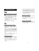
Electrical Connections
Note: All cables must be according to local
electrical codes.
For safety of the users, the pump has to
be grounded.
For BlackStone Pumps:
The pump should be connected to a single
phase power source.
The pump can be mounted directly on a
wall or tank (see pages 12-17 for the spe-
cific mounting dimensions).
Power Requirements
BlackStone pumps
are designed to operate
to specifications within the following voltage
ranges:
100 - 130 Volts for 115V models
200 - 240 Volts for 220V models
To ensure maximum performance, check
the voltage at the point of supply to verify
that it is sufficient. It is recommended that
you install a 1 Amp circuit breaker between
the pump and the power supply. This will
give additional protection to the internal cir-
cuit and provide a convenient way to dis-
connect the power supply prior to servicing
the pump, if needed.
Inside BL7913 and BL7914, for increased
safety, the incoming voltage of either 115 or
240V is reduced to 12V by an isolated trans-
former. With a maximum voltage of 12V
and with the transparent cover installed, risk
of electrical problems is minimized. This
makes the unit safer to operate with.
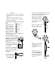
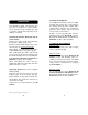
Injection Point
• Choose an injection point that allows you
to mount the injection valve assembly ver-
tically.
• The spring in the injection valve assembly
(HI 721004) adds approximately 1.5 bar of
back pressure. If pumping into a high back
pressure, the spring should be removed.
Other Considerations
• If you are mounting the system to a wall,
column, etc., be sure it is strong enough
to support the weight of the entire system.