
User Guide


2524
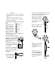
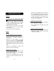
tion valve of the pumphead from the feed
tank. Allow some slack in the hose and be
sure it is not kinked or twisted.
• Slip a hose connector
onto the hose over the
head valve and up to
the bottom of the
threads ensuring it is
fully seated.
• Slide the connector up
to the threads and
tighten to form a seal.
• Slip the ceramic weight
(HI 721008) and a con-
nector over the other end
of the hose.
• Attach the foot valve as-
sembly (HI 721005) to
the hose and slide the
connector up to the
threads and tighten to
form a seal.
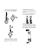
terminals.
• Slide the fitting up, screw it onto the base
and tighten the nut to form the watertight
seal.
• Replace the protective plastic cover.
• Replace the transparent cover and gasket
seal on the front panel.
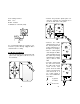
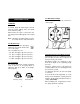
Permanent Connection using 3/8"PVC
pipe
All piping for the
pump feed and dis-
charge should be
plumbed to the lo-
cation of the pump.
The threads on both
valve assemblies
allow the use of
standard 3/8" (Eu-
ropean) pipe fittings
for permanent pipe connections.
The foot valve assembly (HI
721005) should always hang
vertically and not lay hori-
zontal on the bottom of the
tank or drum.
A vertical assembly will en-
sure that the valve is posi-
tioned properly and prevent
loss of prime.
For the U.S. standard in-
stallations, use PVC adapt-
ers to connect the suction
and discharge valves to the
PVC pipe.
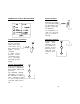
Hose Connections
• Cut a long enough
section of the hose
to reach the suc-
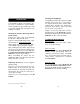
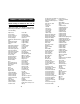
U
NION
C
ONNECTION
A
DAPTER
D
ISCHARGE
V
ALVE
P
UMP
S
UCTION
V
ALVE
A
DAPTER
F
OOT
V
ALVE
F
ILTER
Diagram for Rigid Pipe Hose
-