Instruction Manual BL 7916 - BL 7917 pH and ORP Controller & Dosing Pump http://www.hannainst.
Dear Customer, Thank you for choosing a Hanna product. Please read this instruction manual carefully before using the pump. This manual will provide you with the necessary information for a correct use of the pump, as well as a precise idea of its versatility. If you need additional technical information, do not hesitate to e-mail us at tech@hannainst.com. directives These instruments are in compliance with the EN 50081-1 and EN 50082-1. TABLE OF CONTENTS PRELIMINARY EXAMINATION ...........................
PRELIMINARY EXAMINATION Remove the pump from the packing material and examine it carefully to make sure that no damage has occurred during shipping. If there is any noticeable damage, notify your Dealer. Each pump is supplied complete with: • 7 m (23') LPDE suction and discharge tubing • Power cord • Instruction manual Note: Save all packing material until you are sure that the pump functions correctly. Any defective item must be returned in the original packaging together with the supplied accessories.
overtightening these parts as this could cause damage to the seats and threads. If a hose is used, it should be securely fastened to columns, walls, braces, etc. This will ensure that the hose connection will remain tight and leak free. Shield the hose from direct sunlight. Sunlight can cause an autocatalytic reaction with some chemicals and weaken the hose walls. The arrow on the pump head indicates the direction of chemical flow and should always point upwards (vertically).
FLOW RATE CHART The following chart shows the inverse relationship between flow rate and pressure. The table below shows typical reduction of the flow rate with an increase of pressure. The pump supplied with the system has a capacity of 13.3 LPH (3.5 GPH) at 0.5 BAR (7.4 PSI). BL 7916 / BL 7917 FLOW / PRESSURE BAR (PSI) LPH (GPH) 0.5 (7.4) 13.3 (3.46) 1.0 (14.7) 11.7 (3.04) 2.0 (29.4) 10.1 (2.63) 3.0 (44.1) 9.0 (2.33) 4.0 (58.8) 7.8 (2.
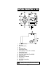
FUNCTIONAL DESCRIPTION BL 7916 1. 2. 3. 4. 5. 6. 7. 8. 9. 10. 11. 12. 13. 14. 15.
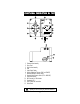
FUNCTIONAL DESCRIPTION BL 7917 1. 2. 3. 4. 5. 6. 7. 8. 9. 10. 11. 12. 13.
SPECIFICATIONS BL7916D BL7916U 0.00 to 14.00 pH Range 0.01 pH Resolution Accuracy (@20°C/68°F) ±0.01 pH Typical EMC Deviation ±0.1 pH High Impedance 10¹² Ohm Input Dosage Proportional: acid or basic. User selectable Dosing Contact Isolated, 2A, Max. 240V, resistive load, 1,000,000 strokes Alarm Contact Isolated, 2A, Max.
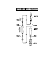
VALVE / HOSE ASSEMBLY DIAGRAM NECK 9
MECHANICAL DIMENSIONS The Controller/Pump series of instruments are enclosed in a modular housing for maximum protection. The dimensioned illustrations show the layout of the Controller/Pumps and how they utilize the one-piece polypropylene, injection-molded housing. Since there are no joints or screws holding different sections of the housing together, the case is extremely rugged and sturdy. BOTTOM VIEW 110mm 4.33" 55mm 2.16" 17mm .67" 142mm 5.60" 129mm 5.08" 99mm 3.90" 5mm 0.
INSTALLATION Materials Needed • LDPE hose (7 meter/22 feet) (included) or other type of tubing (Teflon® for example) more suitable for a specific application (optional) • Power cord (included) Optional Accessories • 4 each, ceramic weights (HI721008) • 1 each, foot valve assembly (HI721005) • 1 each, injection valve assembly (HI721004) Location A suitable location should: • be near to a power source • be conveniently close to the injection point • allow easy access to the flow rate control and pipe or ho
To ensure maximum performance, check the voltage at the point of supply to verify that it is sufficient. It is recommended that you install a 1 Amp circuit breaker between the pump and the power supply. This will give additional protection to the internal circuit and provide a convenient way to disconnect the power supply prior to servicing the pump, if needed. Injection Point • Choose an injection point that allows you to mount the injection valve assembly vertically.
Probe connections Connect the pH/ORP electrode to the BNC socket of the pump. Permanent Connection using 3/8" PVC pipe All piping for the pump feed and discharge should be plumbed to the location of the pump. The threads on both valve assemblies allow the use of standard 3/8" (European) pipe fittings for permanent pipe connections.
Hose Connections • Cut a long enough section of the hose to reach the suction valve of the pump head from the feed tank. Allow some slack in the hose and be sure it is not kinked or twisted. • Slip a hose connector onto the hose over the head valve and up to the bottom of the threads ensuring it is fully seated. • Slide the connector up to the threads and tighten to form a seal. • Slip the ceramic weight (HI721008) and a connector over the other end of the hose.
• Repeat the same installation procedure for the hose connections on the discharge end with the injection assembly (HI721004). • Secure the hose so that its movement is minimized when the pump is operating. Excessive hose movement could cause the connectors to loosen and result in leakage. Assembling the Hose to the Valve The end of the valve is specially tapered to form a leak free seal when the hose is properly installed. Be sure to seat the hose completely so that there is no gap.
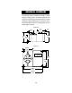
EXAMPLE OF TYPICAL INSTALLATIONS HOSE PIPE PUMP CONNECTION FILTER / FOOT VALVE RESEVOIR CHECK VALVE MANUAL SHUTOFF VALVE LEGEND Flooded Suction Installation Suggested Installation for consistent output when using a low stroke rate. Also suggested for highly viscous chemicals. A slight suction pressure avoids self-priming problems, especially with high viscosity liquids. Suction Lift Installation Suggested installation for most in-line applications with nominal output and pressures.
Downhill Installation Suggested installation when pumping from one container to another, each at different levels and with only nominal pressure. START-UP At start-up, purge all chemical gases and air from the suction tubing, valves and pump head. Start the pump. When all the air or gas is vented, the solution being metered will appear in the output line. Note: only when operating under pressure, the pump must be started unloaded.
OPERATIONAL GUIDE • Unscrew and remove the transparent front panel cover and gasket seal for access to the terminals. • Remove the protective plastic plate covering the terminals by removing the 2 screws on both sides of the plate.
TERMINAL CONNECTIONS BL 7917 Pt100 (for BL 7916 only) A 2-wire Pt100 can be connected to provide automatic temperature compensation of the pH measurements. The pump is supplied with a 100 ohm resistor connected to the 2 Pt100 terminals. This delivers a fixed temperature compensation of 25°C (77°F). The Pt100 is recommended only in special instances where very high accuracy is absolutely necessary since the error is only 0.03 pH for a temperature difference of 10°C in the pH 6 to 8 range.
For example, a level controller can be placed in the tank of the liquid being dosed so that the pump is stopped when the chemicals are exhausted. MANUAL An auxiliary switch can be connected to these terminals to force the unit to pump whatever value is measured by the controller. This might be needed for example when the pump needs to be primed. AUXILIARY CONTACT The controller can drive a relay when the measure overtakes the setpoint. The contact available on the terminals can be normally open or closed.
SETPOINT ADJUSTMENTS • Move the display selector switch to SET. • With a small screwdriver adjust the SET COARSE trimmer to display a value close to the desired setpoint e.g. 7.00. • Adjust the SET FINE trimmer to display the exact setpoint value. • Once the desired setpoint is achieved, move the display selector switch back to MEASURE. ACID OR BASE SELECTION (BL 7916 only) If an acid chemical is to be dosed, move the ACID/BASE switch to ACID.
p H CALIBRATION BL 7916 only: • Ensure that the display selector switch is set to MEASURE and dip the electrode tip in a neutral buffer solution (pH 7.01). • Adjust the OFFSET trimmer to display 7.01 on the LCD. • Rinse the electrode with clean water and dip the electrode tip in pH 4.01 (acidic) or pH 10.01 (alkaline) buffer solution. • Adjust the slope trimmer to read 4.01 or 10.01 on the LCD. The slope calibration with pH 4.
TROUBLESH OOTING GUIDE ELECTRICAL The pump does not operate when turned ON: • Check the power supply and connections. Voltage should be between 100 - 130 VAC for 115 V models and between 200 - 250VAC for 230 V models. • See Installation section on page 11 or call your dealer or the nearest Hanna Customer Service Center for technical assistance. OPERATING Display does not indicate: • Check that the pump is properly plugged in • Check the fuse.
Leakage at the connections: • Be sure that the hose is fully seated and hose connectors are tight. • Be sure that valves are tight and O-rings are in place. Leakage around the pump head: • Be sure that the valves are tight and O-rings are in place and the head screws (hex bolts) are tight. MAINTENANCE Your BlackStone Pump is designed to give you years of trouble-free service. Maintenance should be the preventative type, that is, periodic cleaning and inspecting for any damage or leakage.
SCHEDULED MAINTENANCE After 50 hours Tight the pump head screws with a torque force of 2.5 Nm (22" lbf). After 12 months It is recommended to replace HI721102, HI721103 (suction and discharge valves assemblies) as well as the O-rings. The LDPE hose can also deteriorate over time and, for safety reasons, should also be changed with HI720 032. After 24 months It is recommended to replace HI721102, HI721103, HI720032 and HI721106.
ELECTRODE CONDITIONING AND MAINTENANCE * Only available with refillable electrodes. For industrial applications, gel-filled electrodes are preferable due to lesser maintenance requirements. PREPARATION Remove the protective cap. DO NOT BE ALARMED IF ANY SALT DEPOSITS ARE PRESENT. This is normal with electrodes and they will disappear when rinsed with water. During transport tiny bubbles of air may have formed inside the glass bulb. The electrode cannot function properly under these conditions.
These bubbles can be removed by "shaking down" the electrode as you would do with a glass thermometer. If the bulb and/or junction are dry, soak the electrode in HI 70300 Storage Solution for at least one hour. For refillable electrodes**: If the refill solution (electrolyte) is more than 2½ cm (1") below the fill hole, add HI7082 3.5M KCl Electrolyte Solution for double junction or HI7071 3.5M KCl+AgCl Electrolyte Solution for single junction electrodes.
For refillable electrodes**: Refill the electrode with fresh electrolyte (HI7071 for single junction or HI7082 for double junction electrodes). Allow the electrode to stand upright for 1 hour. Follow the Storage Procedure above. CLEANING PROCEDURE Soak in Hanna HI 7061 General Cleaning Solution for approximately ½ hour. Removal of films, dirt or deposits on the membrane/junction: Protein Soak in Hanna HI 7073 Protein Cleaning Solution for 15 minutes.
• Slow Response/Excessive Drift: Soak the tip in Hanna Solution HI7061 for 30 minutes, rinse thoroughly in distilled water and then follow the Cleaning Procedure above. • For ORP Electrodes: polish the metal tip with a lightly abrasive paper (paying attention not to scratch the surface) and wash thoroughly with water. Note: with industrial applications, it is always recommended to keep at least one spare electrode handy.
TAKING REDOX MEASUREMENTS Redox measurements allow the quantification of the oxidizing or reducing power of a solution, and are commonly expressed in mV. Oxidation may be defined as the process during which a molecule (or an ion) loses electrons and reduction as the process by which electrons are gained. Oxidation is always coupled together with reduction so that as one element gets oxidized, the other is automatically reduced, therefore the term oxidation-reduction is frequently used.
Reducing pretreatment: immerse the electrode for a few minutes in HI 7091. Oxidizing pretreatment: immerse the electrode for a few minutes in HI 7092. If the pretreatment is not performed, the electrode will take significantly longer to respond. As with pH electrodes, gel-filled redox electrodes are more suitable for industrial applications due to lesser maintenance requirements.
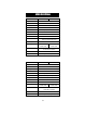
CHEMICAL COMPATIBILITY GUIDE PARTIAL LISTING OF CHEMICALS THAT CAN BE USED WITH BLACKSTONE PUMPS (Rated for 45°C.
Hydrogen Sulfide Aqueous Solution Hypochlorous Acid Kerosene Lactic Acid Lard Oil Lauric Acid Lead Acetate Linoleic Acid Linseed Oil Lithium Salts Magnesium Carbonate Magnesium Chloride Magnesium Hydroxide Magnesium Nitrate Magnesium Oxide Magnesium Sulfate Maleic Acid Malic Acid Mercuric Chloride Methanol Methyl Sulfate Milk Mineral Oils Noptha Petroleum Nickel Chloride Nickel Sulfate Nitric Acid 50% Oils and Fats Oleic Acid Olive Oil Oxalic Acid Palmitric Acid Perchloric Acid 70% Perchloroethylene Petrole
ACCESSORIES SPARE PARTS HI 721102 Discharge Valve (Glass Ball, Valve O-Ring, Hose Connector) TUBE NUT HEAD NIPPLE CHECK SP ACER VALVE VITON® BALL SEAT O-RING HI 721103 Suction Valve (Glass Ball, Valve O-Ring, Hose Connector) VITON® O-RING CHECK VALVE BALL SEAT HEAD NIPPLE TUBE NUT HI 721003 10 x Glass Balls and 10 x Valve O-Rings HI 721004 Injection Valve Assembly INJECTION NIPPLE KYNAR® SPRING CHECK VALVE ASSEMBLY BALL HI 721005 Foot Valve Assembly FILTER FILTER HOLDER HI 721006 4 x Kynar®
HI 721101 HI 721106 Pump head, O-Ring, 6 screws and washers Pump head, Large Teflon® Diaphragm, Aluminum Piston and Aluminum Disk PUMP HEAD DIAPHRAGM pH CALIBRATION SOLUTIONS HI7004M HI7004L HI7006M HI7006L HI7007M HI7007L HI7009M HI7009L HI7010M HI7010L pH 4.01 Buffer Solution, 230 mL pH 4.01 Buffer Solution, 460 mL pH 6.86 Buffer Solution, 230 mL pH 6.86 Buffer Solution, 460 mL pH 7.01 Buffer Solution, 230 mL pH 7.01 Buffer Solution, 460 mL pH 9.18 Buffer Solution, 230 mL pH 9.
HI7073L HI7074M HI7074L HI7077M HI7077L Protein Cleaning Sol., 460 mL Inorganic Cleaning Sol., 230 mL Inorganic Cleaning Sol., 460 mL Oil & Fat Cleaning Sol., 230 mL Oil & Fat Cleaning Sol., 460 mL REFILL ELECTROLYTE SOLUTIONS HI7071 HI7072 HI7082 3.5M KCl+AgCl Electrolyte, 4x50 mL, for single junction electrodes 1M KNO3 Electrolyte, 4x50 mL 3.
HI 1114S Screw connector, double junction plastic-body HI 1134B/3 BNC connector, 3 m (9.9') cable, double junction Ultem®-body with external thread 3/4 x 16 UNF M13 x 1.5 DIA 16 mm DIA 12mm DIA 20.5mm 25 7 mm mm 38.5mm HI 1114S 110mm HI 1134B/3 Screw connector, single junction, refillable with sidearm, glass-body HI 1135B/3 BNC connector, 3 m (9.9') cable, single junction, refillable with side-arm, glass-body HI 1115S M13 x 1.
HI 2114B/5 BNC connector, 5 m (16.5') cable, double junction, Ultem®-body with external thread and cloth junction 3/4 x 16 UNF DIA 12mm DIA 20.5mm 38.5mm 110mm HI 2910B/5 BNC connector, 5 m (16.5') cable, double junction, Ultem®-body with built-in amplifier and cloth junction 3/4 x 16 UNF DIA 12mm DIA 20.5mm 38.5mm 110mm PLATINUM ORP ELECTRODES HI 2930B/5 BNC connector, 5 m (16.
Screw connector, single junction, Pt, refillable with side-arm, glass-body HI 3135B/3 BNC connector, 3 m (9.9') cable, single junction, Pt, refillable with side-arm, glass-body HI 3115S M13 x 1.5 DIA 16 mm 25 7 mm mm HI 3115S HI 3210T HI 3135B/3 Screw connector, external PG13.5 thread, double junction, Pt, Ultem®-body PG13.5 THREAD φ 12mm 30mm 110mm HI 3410S Screw connector, double junction, Pt, Ultem®-body HI 3430B/3 BNC connector, 3 m (9.
HI 4932B/5 BNC connector, 5 m (16.5') cable, double junction, Au, Ultem®-body with built-in amplifier and external thread 3/4 x 16 UNF DIA 12mm DIA 20.5mm 38.5mm 110mm OTHER ACCESSORIES ChecktempC ChecktempF HI 8614 HI 8614L HI 8615 HI 8615L BL PUMPS HI 7871 & HI 7873 HI 6050 & HI 6051 HI 6054 & HI 6057 HI 778P HI 8427 HI 931001 MAN7916R1 Stick Thermometer (range -50.0 to 150.0°C) Stick Thermometer (range -58.
WARRANTY All Hanna Instruments pumps are warranted for one year against defects in workmanship and materials when used for their intended purpose and maintained according to instructions. This warranty is limited to repair or replacement free of charge. Damages due to accident, misuse, tampering or lack of prescribed maintenance are not covered. If service is required, contact the dealer from whom you purchased the instrument.
OTHER PRODUCTS FROM HANNA • • • • • • • • • • • • • • • • • • • • • CABLES AND CONNECTORS CALIBRATION AND MAINTENANCE SOLUTIONS CHEMICAL TEST KITS CHLORINE METERS CONDUCTIVITY/TDS METERS DISSOLVED OXYGEN METERS HYGROMETERS ION SPECIFIC METERS (Colorimeters) MAGNETIC STIRRERS Na/NaCl METERS pH/ORP/Na ELECTRODES pH METERS PROBES (DO, µS/cm, RH, T, TDS) PUMPS REAGENTS SOFTWARE THERMOMETERS TITRATORS TRANSMITTERS TURBIDITY METERS Wide Range of Accessories Most Hanna meters are available in the following forma
CE DECLARATION OF CONFORMITY Recommendations for Users Before using these products, make sure that they are entirely suitable for the environment in which they are used. Operation of these instruments in residential areas could cause unacceptable interference to radio and TV equipment. Any variation introduced by the user to the supplied equipment may degrade the instruments' EMC performance. Unplug the instruments from power supply before replacing the fuse or making any electrical connections.
HANNA LITERATURE POOLS & SPAS WATER ANALYSIS HANDBOOK ENVIROCARE GENERAL CATALOG PRINTED IN PORTUGAL These and many others catalogs, handbooks and leaflets are available from Hanna. To receive your free copy, contact your dealer or the nearest Hanna Customer Service Center. MAN7916R1 02/97 h t t p : / / w w w . h a n n a i n s t .