Instruction Manual BL1.5 • BL3 • BL5 BL7 • BL10 BL15 • BL20 Dosing Pumps www.hannainst.
Dear Customer, Thank you for choosing a Hanna product. Please read this instruction manual carefully before using the pump. If you need additional technical information, do not hesitate to e-mail us at tech@hannainst.com. These instruments are in compliance with the directives. WARRANTY All Hanna Instruments pumps are warranted for one year against defects in workmanship and materials when used for their intended purpose and maintained according to instructions.
Always store chemicals in safe, out of reach places. Follow the directions for use with each chemical. Do not assume chemicals are the same because they look alike. Hanna Instruments cannot be held responsible for the misuse of chemicals or the pump. Always wear protective clothing (gloves and safety glasses) when working near chemical dosing pumps. When pumping chemicals, make sure all tubes are securely attached to the fittings.
The ball valves are constructed in glass. The body is made of fiber-reinforced polypropylene for strength and durability. Reliability through simplicity All BlackStone pumps use the positive displacement solenoid method of pumping. This method has fewer moving parts than a standard motor-driven pump, and does not have the mechanical failures associated with conventional pumps.
BL7 BL7 bar (psi) 0.5 (7.4) 1 (14.7) 2 (29.4) 3 (44.1) 4 (58.8) 5 (73.5) 6 (88.2) 7 (102.9) 8 (117.6) Pump output with 120 strokes/minute 20,0 18,0 16,0 L P H 14,0 12,0 10,0 8,0 6,0 4,0 2,0 0,0 0,5 1 2 3 4 5 6 7 8 BAR BL10 FUNCTIONAL DESCRIPTION lph (gph) 17.2 (4.55) 13.6 (3.60) 10.8 (2.86) 7.6 (2.01) 6.0 (1.59) 5.7 (1.51) 5.4 (1.43) 4.4 (1.16) 3.6 (0.95) BL10 Pump output with 120 strokes/minute 20,0 bar (psi) 0.5 (7.4) 1 (14.7) 2 (29.4) 3 (44.1) 4 (58.8) lph (gph) 18.3 (4.84) 15.2 (4.
SPECIFICATIONS MAX FLOW RATE BL1.5 1.5 lph (0.4 gph) @13 bar (188.5 psi) BL3 2.9 lph (0.8 gph) @ 8 bar (116 psi) BL 5 5.0 lph (1.3 gph) @ 7 bar (101.5 psi) BL7 7.6 lph (2.0 gph) @ 3 bar (43.5 psi) BL10 10.8 lph (2.9 gph) @ 3 bar (43.5 psi) BL15 15.2 lph (4.0 gph) @ 1 bar (14.5 psi) BL20 18.3 lph (4.8 gph) @ 0.5 bar (7.4 psi) Adjustable from 0 to 100% of maximum pump capacity MATERIAL PUMP CASING VALVES PUMPHEAD DIAPHRAGM TUBING Max. height: 1.5 m (5') POWER SUPPLY BL...-1 BL...
INSTALLATION Materials Needed • LDPE hose (7 meter / 22 feet) (included) or other type of tubing (PTFE, for example) more suitable for a specific application (optional) Optional Accessories • 4 each, ceramic weights (HI 721008) Power Requirements BlackStone pumps are designed to operate to specifications within the following voltage ranges: 100 - 130 Volts for -1 models 200 - 240 Volts for -2 models To ensure maximum performance, check the voltage at the point of supply to verify that it is sufficient.
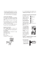
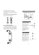
• The pump should be placed in a conventional location that will allow easy access to the control and connections. It should be placed so that regular visual inspections of the connections and hoses are facilitated. Vertical Surface Mounting Once you have selected the best installation site, simply screw or bolt the unit into a wall or mounting panel above the chemical feed tank.
the feed tank. Allow some slack in the hose and be sure it is not kinked or twisted. • Slip a hose connector onto the hose over the head valve and up to the bottom of the threads ensuring it is fully seated. • Repeat the same installation procedure for the hose connections on the discharge end with the injection assembly (HI 721004). • Slide the connector up to the threads and tighten to form a seal. • Slip the ceramic weight (HI 721008) and a connector over the other end of the hose.
Assembling the Hose to the Valve The end of the valve is specially tapered to form a leak free seal when the hose is properly installed. Be sure to seat the hose completely so that there is no gap. Push the hose until it covers the end of the valve completely.
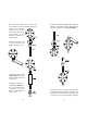
Uphill Installation Suggested installation whenever the supply is located higher than the discharge point; typically a waste water application. It is important to install the Injection valve to prevent siphoning. Downhill Installation Suggested installation when pumping from one container to another, each at different levels and with only nominal pressure. 20 OPERATIONAL GUIDE START-UP At start-up, purge all chemical gases and air from the suction tubing, valves and pump head. Start the pump.
Operating Pressure and Back Pressure Operating pressure is a combination of back pressure plus all of the other resistances to flow present in your system. BlackStone Pumps are designed to dose their rated output at the operating (rated) pressure. Therefore, rated pressure of the pump you install should be close to operating pressure present in the system. Too little back pressure can cause the pump to overdose.
exceed 1.5 meters (5 feet). Either lower the pump or raise the feed tank. • Check the pumphead, suction and discharge valves for blockage. Pump flow rate is reduced: • Check the pumphead, discharge and injection valve assembly for any clogging. Clean and reassemble. • Check for any additional back pressure created since the last flow rate was conducted. • Check for any changes in the viscosity of the chemicals being used.
Cleaning the Pumphead The pumphead should be cleaned at regular intervals and at least once a year. Remove the deposits that form in the cavities with a solution that is neutral to the chemical the pump has been dosing. Inspect the head for any cracks or worn areas. Replace if necessary with parts from the pumphead spare part HI 721106 (for BL7, BL10, BL15 and BL20) or HI 721107 (for BL1.5, BL3 and BL5). SCHEDULED MAINTENANCE After 50 hours Tight the pumphead screws with a torque force of 2.5 Nm (22" lbf).
Hydrochloric Acid (Diluted) Hydrofluoric Acid 60% Hydrogen Sulfide Aqueous Solution Hypochlorous Acid Kerosene Lactic Acid Lard Oil Lauric Acid Lead Acetate Linoleic Acid Linseed Oil Lithium Salts Magnesium Carbonate Magnesium Chloride Magnesium Hydroxide Magnesium Nitrate Magnesium Oxide Magnesium Sulfate Maleic Acid Malic Acid Mercuric Chloride Methanol Methyl Sulfate Milk Mineral Oils Naptha Petroleum Nickel Chloride Nickel Sulfate Nitric Acid 50% Oils and Fats Oleic Acid Olive Oil Oxalic Acid Palmitric
HI 721008 Ceramic Weights, 4 pcs HI 721101 Pumphead, O-Ring, 6 screws and washers (for BL7, BL10, BL15 and BL20) Pumphead Large PTFE Diaphragm Aluminum Piston Aluminum Disk HI 721106 HI 721107 (for BL1.5, BL3 and BL5) Pump-head Small PTFE Diaphragm Aluminum Piston OTHER ACCESSORIES HI 731326 Calibration screwdriver (20 pcs) CE DECLARATION OF CONFORMITY Recommendations for Users Before using these products, make sure that they are entirely suitable for the environment in which they are used.
SALES AND TECHNICAL SERVICE CONTACTS Australia: Tel. (03) 9769.0666 • Fax (03) 9769.0699 China: Tel. (10) 88570068 • Fax (10) 88570060 Egypt: Tel. & Fax (02) 2758.683 Germany: Tel. (07851) 9129-0 • Fax (07851) 9129-99 Greece: Tel. (210) 823.5192 • Fax (210) 884.0210 Indonesia: Tel. (21) 4584.2941 • Fax (21) 4584.2942 Japan: Tel. (03) 3258.9565 • Fax (03) 3258.9567 Korea: Tel. (02) 2278.5147 • Fax (02) 2264.1729 Malaysia: Tel. (603) 5638.9940 • Fax (603) 5638.9829 Singapore: Tel. 6296.