Instruction Manual C 216 & C 226 Multiparameter Bench Photometers for Pool & Spa Applications These Instruments are in Compliance with the CE Directives www.hannainst.
Dear Customer, Thank you for choosing a Hanna product. Please read this instruction manual carefully before using the meter. This manual will provide you with the necessary information for the correct use of the instrument. If you need additional technical information, do not hesitate to e-mail us at tech@hannainst.com. These instruments are in compliance with directives. TABLE OF CONTENTS CALCIUM HARDNESS ..................... 26 FREE CHLORINE ............................ 28 TOTAL CHLORINE ...............
PRELIMINARY EXAMINATION Please examine this product carefully. Make sure that the instrument is not damaged. If any damage occured during shipment, please notify your Dealer. Each Meter is supplied complete with: • Four Sample Cuvets and Caps • Two 9V Batteries • One pair of scissors • Instruction Manual • Rigid carrying case Note: Save all packing material until you are sure that the instrument works correctly. Any defective item must be returned in its original packing with the supplied accessories.
GENERAL DESCRIPTION C 99 & C 200 Series is a line of 17 different bench, microprocessorbased photometers to measure more than 50 different parameters in water and wastewater.
SIGNIFICANCE OF POOL AND SPA TESTING A major family leisure pursuit is the enjoyment of Swimming Pool and Spa facilities world-wide. A basic necessity of Pool water treatment, to ensure such enjoyment, is to maintain the water in a safe and pleasant condition for the bathers. In order to achieve such an objective, swimming pool water requires testing on daily, and sometimes hourly bases for disinfection residuals and pH.
between the hypochlorous acid (HOCl) and the hypochlorite ions (OCl-). Although both forms are considered free chlorine, it is the hypochlorous acid that provides the strongest disinfecting and oxidising characteristic of chlorine solutions. The amount of hypochlorous acid in chlorinated water dependends upon the pH value of the solution. Changes in pH value will effect the HOCl equilibrium in relation to the hydrogen and hypochlorite ion.
frequently large amounts of pool water. In general its application is found just before water passes through the filter units. Its sanitizing power is not pH related. Mainly because of its strong oxidizing power the return water may contain only trace concentrations of ozone. It has to be mentioned that ozone is very unstable and there is anyway the need for low-level chlorination to ensure sanitizing throughout the whole pool.
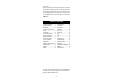
rate increases. If the alkalinity values are sufficiently high it will not be difficult to control the pH. Most pools managers do prefer to keep the pH between 7.2 and 7.4, that does ensure low corrosion rates and a sufficient activity of chlorine. Langelier Index (LI) The Langelier Index is a powerful tool to calculate the water balance, and to predict corrosion or scaling problems. Theoretically, a LI of zero indicates perfect water condition for swimming pools.
Water Balance Condition of Water 11.0 – 12.0 12.1 – 12.3 12.4 – 12.6 12.7 – 12.9 13.0 – 14.0 Recommendation Corrosive Increase pH and/or Alkalinity Acceptable Balance Retest water frequently Ideal Balance Acceptable Balance Retest water frequently Scale forming Reduce pH and/or alkalinity WATER INDEX REFERENCE TABLES Temperature TF °C °F 0 4 8 12 16 20 24 28 32 36 40 50 32 39 46 54 60 68 75 82 90 97 104 122 Calcium Hardness mg/L HF (as CaCO3) 0 0.1 0.2 0.3 0.4 0.5 0.6 0.7 0.7 0.8 0.9 1.
SPECIFICATIONS Life of the instrument Silicon Photocell 0 to 50°C (32 to 122°F); max 90% RH non-condensing Power Supply 2 x 9 V batteries / 12 to 20 VDC through voltage adapter (optional) Auto-Shut off After 10' of non-use Dimensions 230 x 165 x 70 mm (9.0 x 6.5 x 2.8") Weight 640 g (22.6 oz.) For specifications related to each single parameter (e.g. range, precision, etc.), refer to the related measurement section.
PRINCIPLE OF OPERATION Absorption of Light is a typical phenomenon of interaction between electromagnetic radiation and matter. When a light beam crosses a substance, some of the radiation may be absorbed by atoms, molecules or crystal lattices.
A microprocessor controlled special tungsten lamp emits radiation which is first optically conditioned and beamed to the sample contained in the cuvet. The optical path is fixed by the diameter of the cuvet. Then the light is spectrally filtered to a narrow spectral bandwidth, to obtain a light beam of intensity Io or I. The photoelectric cell collects the radiation I that is not absorbed by the sample and converts it into an electric current, producing a potential in the mV range.
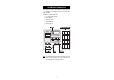
FUNCTIONAL DESCRIPTION FRONT PANEL 1) 2) 3) 4) 5) Cuvet Holder Dual Level Liquid Crystal Display (LCD) Programs List READ DIRECT, to perform measurement immediately TIMER, to perform measurement after a preprogrammed countdown 6) ZERO, to zero the meter prior to measurement 7) Program ▼ and ▲, to select the desired parameter 8) ON/OFF, to turn the meter on and off REAR PANEL 1) Power Supply 12 VDC 2.
GUIDE TO DISPLAY CODES Note: The secondary LCD below shows a generic "P– –", whereas the meter will indicate the exact program number (e.g. in C 216, "P1" for Alkalinity). This indicates that the meter is in a ready state and zeroing can be performed. Sampling in progress. This flashing prompt appears each time the meter is performing a measurement. The microprocessor is adjusting the light level, indicated by a scrolling "SIP".
The lamp is not working properly. Contact your dealer or the nearest Hanna Customer Service Center. The lamp is not working properly. Contact your dealer or the nearest Hanna Customer Service Center. This indicates that the meter has lost its configuration. Contact your dealer or the nearest Hanna Customer Service Center. ERROR MESSAGES a) on zero reading: This indicates that the zeroing procedure failed due to a low signal-to-noise ratio. In this case press ZERO again.
A zero reading was not taken. Follow the instruction described in the measurement procedures for zeroing the meter. Under range. A blinking "0.00" indicates that the sample absorbs less light than the zero reference. Check the procedure and make sure that you use the same cuvet for reference (zero) and measurement. 1) A flashing value of the maximum concentration indicates an over range condition. The concentration of the sample is beyond the programmed range: dilute the sample and rerun the test.
TIPS FOR AN ACCURATE MEASUREMENT The instructions listed below should be carefully followed during testing to ensure best accuracy. • Color or suspended matter in large amounts may cause interference, therefore, these should be removed by treatment with active carbon and by prior filtration. • For a correct filling of the cuvet: the liquid in the cuvet forms a convexity on the top; the bottom of this convexity must be at the same level of the 10 mL mark.
• In order to avoid reagent leaking and to obtain more accurate measurements, it is recommended to close the cuvet first with the supplied HDPE plastic stopper and then with the black cap. • Each time the cuvet is used, the cap must be tightened to the same degree. • Whenever the cuvet is placed into the measurement cell, it must be dry outside, and completely free of fingerprints, oil or dirt.
PARAMETERS REFERENCE TABLES C 216 - POOLMETER C 226 - POOLMETER Code Parameter 1 Alkalinity Code Parameter 1 Alkalinity Page 22 Page 22 2 Ca Hardness 3 Free Chlorine 26 28 2 Bromine 3 Ca Hardness 24 26 4 Total Chlorine 5 Cyanuric Acid 6 pH 30 36 44 4 Free Chlorine 5 Total Chlorine 6 Free Copper 28 30 32 7 Total Copper 8 Cyanuric Acid 34 36 9 Iron 10 Ozone 11 pH 19 38 40 44
OPERATIONAL GUIDE POWER CONNECTION Remove the battery cover on the back of the meter; attach 2 fresh 9V batteries and replace the cover. Alternatively, plug the optional 12VDC adapter (HI 710005 - 110VDC, or HI 710006 - 220VDC) into the DC socket. Plug the adapter into the outlet. Note: Insure the main line is surge protected. Note: Always turn the meter off before unplugging it to insure no data is lost. MEASUREMENT PROCEDURE • Turn the meter on by pressing ON/OFF.
• After the desired program number appears on the secondary display, follow the measurement procedure described in the related chapter. • Select a new parameter measurement procedure by pressing the PROGRAM ▼ and PROGRAM ▲ keys. Note: in the following measurement sections, a generic "P– –" will be placed on the secondary LCD instead of the exact related message (e.g. in C 226, "P2" for Bromine). • Before performing a test read carefully all the instructions related to the selected parameter.
ALKALINITY SPECIFICATIONS Range Resolution Precision Typical EMC Deviation Light Source Method 0 to 500 mg/L (as CaCO3) 5 mg/L ±10 @ 100 mg/L ±5 mg/L Tungsten lamp with narrow band interference filter @ 575 nm Colorimetric Method. At different alkalinity levels a distinctive range of colors from yellow to green and greenish blue will develop.
• Wait for a few seconds and the display will show “-0.0-”. Now the meter is zeroed and ready for measurement. • Remove the cuvet. • Add carefully the content of one packet of HI 93755-0 Alkalinity Indicator Reagent. Replace the cap and shake vigorously for 30 seconds. Note: Pay attention not to spill reagent otherwise full color development may be inhibithed. • Replace the cuvet into the holder and ensure that the notch on the cap is positioned securely into the groove.
BROMINE SPECIFICATIONS Range Resolution Precision Typical EMC Deviation Light Source Method 0.00 to 10.00 mg/L 0.01 mg/L ±0.05 mg/L @ 2.00 mg/L ±0.01 mg/L Tungsten lamp with narrow band interference filter @ 525 nm Adaptation of the Standard Methods for the Examination of Water and Wastewater, 20th edition, DPD method. The reaction between bromine and the reagent causes a pink tint in the sample.
• Wait for a few seconds and the display will show “-0.0-”. Now the meter is zeroed and ready for measurement. • Remove the cuvet. • Add the content of one packet of HI 93716-0 Bromine Reagent. Replace the cap and shake gently for about 20 seconds to dissolve most of the reagent. • Replace the cuvet into the holder and ensure that the notch on the cap is positioned securely into the groove. • Press TIMER and the display will show the countdown prior to measurement.
CALCIUM HARDNESS SPECIFICATIONS Range Resolution Precision Typical EMC Deviation Light Source Method 0 to 500 mg/L (as CaCO3) 5 mg/L ±10 mg/L @ 200 mg/L ±5 mg/L Tungsten lamp with narrow band interference filter @ 525 nm Colorimetric Method. The reaction between calcium and the reagents causes a violet to orange tint in the sample.
• Remove the cuvet. • Add carefully the content of one packet of HI 93756A-0 Ca Hardness 1 Reagent. Replace the cap and shake vigorously for 10 seconds. Note: Pay attention not to spill reagent otherwise full color development may be inhibithed. • Add the content of one packet of HI 93756B-0 Ca Hardness 2 Reagent. Replace the cap and shake vigorously for 10 seconds. • Replace the cuvet into the holder and ensure that the notch on the cap is positioned securely into the groove.
FREE CHLORINE SPECIFICATIONS Range Resolution Precision Typical EMC Deviation Light Source Method 0.00 to 5.00 mg/L 0.01 mg/L from 0.00 to 2.50 mg/L; 0.10 mg/L above 2.50 mg/L ±0.03 mg/L @ 1.00 mg/L ±0.01 mg/L Tungsten lamp with narrow band interference filter @ 525 nm Adaptation of the USEPA method 330.5 and Standard Methods for the Examination of Water and Wastewater, 20th edition, 4500-Cl G. The reaction between free chlorine and the DPD reagent causes a pink tint in the sample.
• Wait for a few seconds and the display will show “-0.0-”. Now the meter is zeroed and ready for measurement. • Remove the cuvet. • Add the content of one packet of HI 93701-0 Free Chlorine Reagent. Replace the cap and shake gently for 20 seconds. • Replace the cuvet into the holder and ensure that the notch on the cap is positioned securely into the groove. • Wait for 1 minute and press READ DIRECT. “SIP” will blink during measurement.
TOTAL CHLORINE SPECIFICATIONS Range Resolution Precision Typical EMC Deviation Light Source Method 0.00 to 5.00 mg/L 0.01 mg/L from 0.00 to 2.50 mg/L; 0.10 mg/L above 2.50 mg/L ±0.03 mg/L @ 1.00 mg/L ±0.01 mg/L Tungsten lamp with narrow band interference filter @ 525 nm Adaptation of the EPA method 330.5 and Standard Methods for the Examination of Water and Wastewater, 20th edition, 4500-Cl G. The reaction between chlorine and the DPD reagent causes a pink tint in the sample.
• Wait for a few seconds and the display will show “-0.0-”. Now the meter is zeroed and ready for measurement. • Remove the cuvet. • Add the content of one packet of HI 93711-0 Total Chlorine Reagent. Replace the cap and shake gently for 20 seconds • Replace the cuvet into the holder and ensure that the notch on the cap is positioned securely into the groove. • Press TIMER and the display will show the countdown prior to measurement. Alternatively, wait for 2 minutes and 30 seconds and press READ DIRECT.
FREE COPPER SPECIFICATIONS Range Resolution Precision Typical EMC Deviation Light Source Method 0.00 to 5.00 mg/L 0.01 mg/L ±0.03 mg/L @ 1.00 mg/L ±0.01 mg/L Tungsten lamp with narrow band interference filter @ 575 nm Adaptation of the USEPA approved method. The reaction between free copper and the bicinchoninate reagent causes a purple tint in the sample.
• Wait for a few seconds and the display will show “-0.0-”. Now the meter is zeroed and ready for measurement. • Remove the cuvet. • Add the content of one packet of HI 93702-0 Copper Reagent. Replace the cap and shake gently for 15 seconds. • Replace the cuvet into the holder and ensure that the notch on the cap is positioned securely into the groove. • Press TIMER and the display will show the countdown prior to measurement. Alternatively, wait for 45 seconds and press READ DIRECT.
TOTAL COPPER SPECIFICATIONS Range Resolution Precision Typical EMC Deviation Light Source Method 0.00 to 5.00 mg/L 0.01 mg/L ±0.03 mg/L @ 1.00 mg/L ±0.01 mg/L Tungsten lamp with narrow band interference filter @ 575 nm Adaptation of the USEPA approved method. The reaction between free copper and the bicinchoninate reagent causes a purple tint in the sample.
• Wait for a few seconds and the display will show “-0.0-”. Now the meter is zeroed and ready for measurement. • Remove the cuvet. • Add the content of one packet of HI 93702-0 Copper Reagent. Replace the cap and shake gently for 15 seconds. • Add the content of one packet of HI 93702T-0 Copper Total Reagent. Replace the cap and shake vigorously for 15 seconds. • Replace the cuvet into the holder and ensure that the notch on the cap is positioned securely into the groove.
CYANURIC ACID SPECIFICATIONS Range Resolution Precision Typical EMC Deviation Light Source Method 0 to 200 mg/L 1 mg/L from 0 to 100 mg/L; 10 mg/L above 100 mg/L ±5 mg/L @ 60 mg/L ±1 mg/L Tungsten lamp with narrow band interference filter @ 525 nm Turbidimetric method. The reaction between cyanuric acid and the reagent causes a white turbidity in the sample.
• Wait for a few seconds and the display will show “-0.0-”. Now the meter is zeroed and ready for measurement. • Remove the cuvet. • Add the content of one packet of HI 93722-0 Cyanuric Acid Reagent. Replace the cap and shake gently for about 10 seconds (dissolution is not complete). • Replace the cuvet into the holder and ensure that the notch on the cap is positioned securely into the groove. • Press TIMER and the display will show the countdown prior to measurement.
IRON SPECIFICATIONS Range Resolution Precision Typical EMC Deviation Light Source Method 0.00 to 5.00 mg/L 0.01 mg/L ±0.02 mg/L @ 1.50 mg/L ±0.01 mg/L Tungsten lamp with narrow band interference filter @ 525 nm Adaptation of the EPA method 315B and Standard Methods for the Examination of Water and Wastewater, 20th edition, 3500-Fe B. The reaction between iron and the phenantroline reagent causes an orange tint in the sample.
• Wait for a few seconds and the display will show “-0.0-”. Now the meter is zeroed and ready for measurement. • Remove the cuvet. • Add the content of one packet of HI 93721-0 Iron High Range Reagent. Replace the cap and shake until dissolution is complete. • Replace the cuvet into the holder and ensure that the notch on the cap is positioned securely into the groove. • Press TIMER and the display will show the countdown prior to measurement. Alternatively, wait for 3 minute and press READ DIRECT.
OZONE SPECIFICATIONS Range Resolution Precision Typical EMC Deviation Light Source Method 0.00 to 2.00 mg/L 0.01 mg/L ±0.03 mg/L @ 1.00 mg/L ±0.01 mg/L Tungsten lamp with narrow band interference filter @ 525 nm Colorimetric DPD Method. The reaction between ozone and the DPD reagent causes a pink tint in the sample.
STANDARD MEASUREMENT PROCEDURE • Select the program number corresponding to Ozone on the secondary LCD by pressing PROGRAM ▼ and ▲. • Fill the cuvet with 10 mL of unreacted sample, up to the mark, and replace the cap. 10 mL • Place the cuvet into the holder and ensure that the notch on the cap is positioned securely into the groove. • Press ZERO and “SIP” will blink on the display. • Wait for a few seconds and the display will show “-0.0-”. Now the meter is zeroed and ready for measurement.
ADDITIONAL MEASUREMENT PROCEDURE For samples containing chlorine • Select the program number corresponding to Ozone on the secondary LCD by pressing PROGRAM ▼ and ▲. • Fill the cuvet with 10 mL of unreacted sample, up to the mark, and replace the cap. • Place the cuvet into the holder and ensure that the notch on the cap is positioned securely into the groove. • Press ZERO and “SIP” will blink on the display. • Wait for a few seconds and the display will show “-0.0-”.
• Press TIMER and the display will show the countdown prior to measurement. Alternatively, wait for 2 minutes and press READ DIRECT. In both cases “SIP” will blink during measurement. • The instrument directly displays a concentration value refering to chlorine interference, on the Liquid Crystal Display. Subtract this value from the reading from the Standard Measurement Procedure: this will be the concentration in mg/L of ozone in the sample.
pH SPECIFICATIONS Range Resolution Precision Typical EMC Deviation Light Source Method 6.5 to 8.5 pH 0.1 pH ±0.1 pH ±0.1 pH Tungsten lamp with narrow band interference filter @ 525 nm Adaptation of the Phenol Red method. The reaction between the sample and the reagent causes a yellow to a red tint in the sample.
• Wait for a few seconds and the display will show “-0.0-”. Now the meter is zeroed and ready for measurement. • Remove the cuvet. • Add 5 drops of HI 93710-0 pH Reagent. Replace the cap and swirl the cuvet. • Replace the cuvet into the holder and ensure that the notch on the cap is positioned securely into the groove. • Press READ DIRECT and “SIP” will blink during measurement. • The instrument directly displays the pH measured value on the Liquid Crystal Display.
INTERFACE WITH PC To connect your meter to the PC use the optional HI 920010 (available from your Hanna Dealer). Make sure that your meter is switched off and plug the connectors, one into the meter RS 232C socket, the other into the serial port of your PC. Note: Cables other than HI 920010 may use a different configuration, in which case, communication between the meter and the PC may not be possible.
/PUP - Program Up /PDN - Program Down /PTM - Turn Test Mode On /Brx - Set the baud rate 1 - 300 2 - 600 3 - 1200 4 - 2400 /KBL - Lock Keyboard /KBU - Unlock Keyboard ?PR# - Send Current Program Number ?BRQ - Send current baud rate 1 - 150 2 - 300 3 - 600 4 - 1200 5 - 2400 ?CNQ - Send Concentration (three bytes) conc decimal point unit m - ppm b - ppb t - ppt u - pcu h - pH ?ERR - send error / status information 0 - No error 1 - CAP 2 - HI 3 - ZERO 4 - LO 5 - IDLE 6 - ZERO DONE 7 - TIMED READ 47
STANDARD METHODS Description Alcalinity Bromine Calcium Hardness Chlorine, Free Chlorine, Total Copper, Free Copper, Total Cyanuric Acid Iron Ozone pH Range 0 to 500 mg / L 0.00 to 10.00 mg / L 0 to 500 mg / L 0.00 to 5.00 mg / L 0.00 to 5.00 mg / L 0.00 to 5.00 mg / L 0.00 to 5.00 mg / L 0 to 200 mg / L 0.00 to 5.00 mg / L 0.00 to 2.00 mg / L 6.5 to 8.
ACCESSORIES REAGENT SETS HI 93701-01 100 free chlorine tests (powder) HI 93701-03 300 free chlorine tests (powder) HI 93702-01 100 free copper tests HI 93702-03 300 free copper tests HI 93702T-01 100 total copper tests HI 93702T-03 300 total copper tests HI 93703-52 100 glycine powder packets (optional reagent) HI 93710-01 100 pH tests HI 93710-03 300 pH tests HI 93711-01 100 total chlorine tests (powder) HI 93711-03 300 total chlorine tests (powder) HI 93716-01 100 bromine tests HI 93716-03 300 bromine tes
CE DECLARATION OF CONFORMITY Recommendations for Users Before using these products, make sure that they are entirely suitable for your specific application and for the environment in which they are used. Operation of these instruments may cause unacceptable interferences to other electronic equipments, this requiring the operator to take all necessary steps to correct interferences. Any variation introduced by the user to the supplied equipment may degrade the instruments' EMC performance.
WARRANTY All Hanna Instruments meters are warranted for two years against defects in workmanship and materials when used for its intended purpose and maintained according to the instructions. This warranty is limited to repair or replacement free of charge. Damages due to accident, misuse, tampering or lack of prescribed maintenance are not covered. If service is required, contact your dealer. If under warranty, report the model number, date of purchase, serial number and the nature of the failure.
MANC216R2 01/03 w w w . h a n n a 52 i n s t .