EC 700 TDS 705 EC 710 Process, Panel-mounted, Microprocessor-based, Conductivity and TDS Controllers Instruction Manual
Dear Customer, Thank you for choosing a Hanna Product. This instruction manual has been written for the following products: EC 700 EC controller with dual setpoint, ON/OFF and PID control, analog output TDS 705 TDS controller with dual setpoint, ON/OFF and PID control, analog output EC 710 EC and TDS controller with dual setpoint, ON/OFF and PID control, analog output TABLE OF CONTENTS PRELIMINARY EXAMINATION . . . . . . . . . . . . . . . . . . 4 GENERAL DESCRIPTION . . . . . . . . . . . . . . . . . . . .
PRELIMINARY EXAMINATION Remove the instrument from the packing material and examine it carefully to make sure that no damage has occurred during shipping. If there is any noticeable damage, notify your Dealer or the nearest Hanna Customer Service Center immediately. Note Save all packing materials until you are sure that the instrument functions correctly. Any damaged or defective items must be returned in their original packing materials together with the supplied accessories.
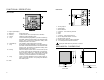
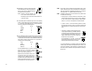
FUNCTIONAL DESCRIPTION REAR PANEL FRONT PANEL 1. 2. 3. 4. 5. 6. 7. 8. 9. 10. Liquid Crystal Display SETUP key enters setup mode CFM key confirms current choice (and skips to the next item) CAL key initiates and exits calibration mode ! key increases the blinking digit/letter by one when selecting a parameter. Advances forward while in last calibration data viewing mode.
SPECIFICATIONS INSTALLATION Ranges 0.0 to 199.9 µS, 0 to 1999 µS (EC 700, EC 710 only) 0.00 to 19.99 mS, 0.0 to 199.9 mS (EC 700, EC 710 only) 0.0 to 100.0 ppm, 0 to 1000 ppm (TDS 705, EC710* only) 0.00 to 10.00 ppt, 0.0 to 100.0 ppt (TDS 705, EC710* only) -10.0 to 100.0 °C Resolution 0.1 µS, 1 µS (EC 700, EC 710 only) 0.01 mS, 0.1 mS (EC 700, EC 710 only) 0.1 ppm, 1 ppm (TDS 705, EC710 only) 0.01 ppm, 0.1 ppm (TDS 705, EC710 only) 0.1 °C Accuracy ±0.5 % full scale (EC and TDS) ±0.
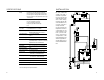
• Power Supply: Connect a 3-wire power cable to the terminal strip, while paying attention to the correct live (L), earth (PE) and neutral (N) terminal connections. Power: 115VAC -100 mA / 230VAC - 50 mA. Live Contact: fused inside 200mA. PE leakage current 1 mA; this contact must be connected to ground. • Conductivity input: the default input is from conductivity probe. Connect the EC probe to the terminals #9 on page 7.
SETUP MODE • Then confirm the displayed digit with # and move to the next one. EC 700, TDS 705 and EC 710 offer a multitude of possibilities from ON/OFF or PID dosage to analog recorder output and from alarm to selftest features. The Setup Mode allows the user to set all needed characteristics of the meter. The setup mode is entered by pressing SETUP and entering the password when the device is in idle or control mode.
• After confirmation, the selected parameter is displayed. The user can scroll through the parameters by pressing CFM. In order to directly set another parameter, press SETUP again and enter the code or scroll to it by pressing CFM. The following table lists the setup codes along with the description of the specific setup items, their valid values and whether password is required to view that item (“PW” column): 14 Code Valid Values Default PW 14 Relay 1 deviation (D1) 0.5 to 10% f.s. 1% f.s.
Note Code Valid Values Default PW 60 Current day 01 to 31 from RTC no 61 Current month 01 to 12 from RTC no 62 Current year 1998 to 9999 from RTC no 63 Current time 00:00 to 23:59 from RTC no 72 Cleaning timer 0 to 9999 days 0 no 73 Initial cleaning day 01 to 31 01 no 74 Initial cleaning month 01 to 12 01 no 75 Initial cleaning year 1998 to 9999 1998 no 76 Initial cleaning time 00:00 to 23:59 00:00 no 77 Cleaning ON interval 0 to 19999 minutes 0 no 90 Display sel
CONTROL MODE The control mode is the normal operational mode for these meters. During control mode the meter fulfills the following main tasks: • converts information from EC/TDS and temperature inputs to digital values; • controls relays and generates the analog outputs as determined by the setup configuration, displays alarm condition; In EC 710 model it is possible to switch between EC and TDS reading pressing “LCD”.
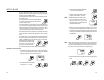
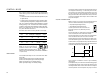
dition of low or high conductivity solution. An example of how the response overshoot can be improved with a proper rate action setting is depicted in the following graphic. control a low conductivity dosing pump. ON EC OFF Setpoint Setpoint + Hysteresis EC P.I.D. CONTROL MODE PID control is designed to eliminate the cycling associated with ON/OFF control in a rapid and steady way by means of the combination of the proportional, integral and derivative control methods.
The proportional action is set through the setup procedure as “Deviation” in percent of full scale of the selected range. Each setpoint has a selectable deviation: D1 for setpoint1 and D2 for setpoint2. Two further parameters must be provided for both setpoints: Ti = Kp/Ki, reset time, measured in minutes Td = Kd/Kp, rate time, measured in minutes. Ti1 and Td1 will be the reset time and rate time for setpoint1, while Ti2 and Td2 will be the reset time and the rate time for setpoint2.
This is an important feature since with most meters the alarm terminals close only when an abnormal situation arises, however, due to line interruption, no alarm is sounded, causing extensive damage. On the other hand, software is employed to set off the alarm in abnormal circumstances, for example, if the dosing terminals are closed for too long a period. In both cases, the red LED’s will also provide a visual warning signal.
IDLE MODE ANALOG OUTPUT Idle mode is entered through setup code 2. During idle mode the device performs the same tasks as when it is in control mode except for the relays. The alarm relay is activated (no alarm condition), the control relays are not activated while the analog output remains activated. When the instrument is in idle mode the red and green status LEDs are on. All models are provided with the analog output feature. The output is isolated and can be a voltage or a current.
output matching a different EC or TDS range, for example, 4 mA = 30 mS and 20 mA = 50 mS. To change the default values, the setup mode must be entered. Setup codes for changing the analog output minimum and maximum are 41 or 42, respectively. For the exact procedure, refer to the setup mode section in the manual. Note The analog output is factory calibrated through software. The user may also perform the calibration procedure as explained in the following.
If the zero calibration cannot be performed, "ERROR" will blink. Cell constant calibration • Select the solution value on the primary display by pressing ! or " if the selected range has two possibilities (e.g. 5.000 and 12.880 mS). • Immerse the EC/TDS probe with the temperature sensor in the selected solution. The level of solution must be higher than the holes of the EC/TDS probe sleeve.
• Press SETUP key. • Using !, " and # , enter the desired buffer value and confirm by pressing CFM. Calibration procedure may be interrupted by pressing CAL again at any time. If the calibration procedure is stopped this way, or if the controller is switched off before the last step, no calibration data is stored in non-volatile memory (EEPROM). ANALOG INPUT CALIBRATION Note Note Press SETUP before CFM to exit without changes.
• Use the ! or " to make the HI 931002 or multimeter output correspond with the meter’s value shown on the secondary display (e.g. 4). • Wait for approximately 30 seconds (until the reading of the calibrator is stable). • Press CFM to confirm. The meter will switch to the second calibration point. Repeat the above procedure. way, or if the controller is switched off before the last step, no calibration data is stored in non-volatile memory (EEPROM).
FAULT CONDITIONS AND SELFTEST PROCEDURES LAST CALIBRATION DATA The meter can display the following last calibration data: • Date • Time • Cell constant While displaying these data, the controller remains in control mode. The data are related to the selected range only. The procedure below indicates the flow. Displaying of the items follows the above sequence. • To begin the cycle press CAL DATA. The last calibration date will appear on the primary LCD as DD.
scrolling "Display test" message. EEPROM SELFTEST The EEPROM selftest procedure involves verifying the stored EEPROM checksum. If the checksum is correct the “Stored data good” message will be shown for a few seconds before exiting selftest procedure. The segments are lit for a few seconds and then switched off before exiting the selftest procedure. KEYBOARD SELFTEST If not, the message “Stored data error - Press ! to reset stored data or # to ignore”.
WATCHDOG When a dead loop condition is detected a reset is automatically invoked. The effectiveness of watchdog capability can be tested through one of the special setup items. This test consists of executing a dummy dead loop that causes watchdog reset signal to be generated. EXTERNAL FUNCTIONS HOLD FUNCTION This function allows to perform the maintenance procedures.
EC VALUES AT VARIOUS TEMPERATURES EC / TDS PROBE MAINTENANCE Temperature has a significant effect on conductivity. Table below shows EC values at various temperatures for the Hanna calibration solutions. TEMPERATURE °C °F HI7030 HI8030 42 EC VALUES (µS/cm) HI7031 HI7033 HI7034 HI7035 HI8031 HI8033 HI8034 HI8035 HI7039 HI8039 0 32 7150 776 64 48300 65400 2760 5 41 8220 896 65 53500 74100 3180 10 50 9330 1020 67 59600 83200 3615 15 59 10480 1147 68 65400 92500 4063 16 60.
ACCESSORIES CONDUCTIVITY & TDS BUFFER SOLUTIONS HI 7030L 12880 µS/cm (µmho/cm), 460mL HI 7030M 12880 µS/cm (µmho/cm), 230mL HI 7031L 1413 µS/cm (µmho/cm), 460mL HI 7031M 1413 µS/cm (µmho/cm), 230mL HI 7033L 84 µS/cm (µmho/cm), 460 mL HI 7033M 84 µS/cm (µmho/cm), 230 mL HI 7034L 80000 µS/cm (µmho/cm), 460mL HI 7034M 80000 µS/cm (µmho/cm), 230mL HI 7035L 111800 µS/cm (µmho/cm), 460mL HI 7035M 111800 µS/cm (µmho/cm), 230mL HI 7039L 5000 µS/cm (µmho/cm), 460mL HI 7039M 5000 µS/cm (µmho/cm), 230mL HI 7032L 1382
WARRANTY CE DECLARATION OF CONFORMITY All Hanna Instruments meters are guaranteed for two years against defects in workmanship and materials when used for their intended purpose and maintained according to instructions. The probes are guaranteed for a period of six months. This warranty is limited to repair or replacement free of charge. Damage due to accident, misuse, tampering or lack of prescribed maintenance are not covered.
HANNA LITERATURE Water Analysis Handbook Water Treatment General Catalog PRINTED IN PORTUGAL Lab Recording h t t p : / / w w w . h a n n a i n s t . c o m MANEC700R1 04/99 These and many others catalogs, handbooks and leaflets are available from Hanna. To receive your free copy, contact your dealer or the nearest Hanna Customer Service Center.