
User's Manual


19
NORMAL OPERATION &NORMAL OPERATION &
NORMAL OPERATION &NORMAL OPERATION &
NORMAL OPERATION &
MEASUREMENTMEASUREMENT
MEASUREMENTMEASUREMENT
MEASUREMENT
Make sure that the controller has been properly calibrated before
commencing and that the pH and conductivity/TDS setpoints have
been adjusted (see following pages).
The pH electrode, conductivity/TDS probe and any ground probe
must be properly connected and wired to the controller (see preceding
pages).
The conductivity/TDS probe’s protective sleeve must not be removed
and the holes on the sleeve should be near the top (the cable end).
The probe must be immersed in the solution above the air-vent holes
on the external sleeve. The probe must be installed in such a way as
to minimize presence of air bubbles (see probe installation tips at the
end of the manual).
Remove the protective cap if it is still on the tip of the pH electrode
and ensure that the electrode is immersed in the solution (at least
4cm/1.5”). The electrode should be installed in such a away that it
permanently lies in the solution whether in a well, tank or on the
discharge pipe.
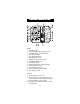
The controller provides for visual dosing status through two LED’s (see
3 and 11 - Functional Dia-
gram). The LED’s light up when
the controller is in the pH and/
or conductivity/TDS dosage
mode and the relays are acti-
vated.
The actual pH and conductivity or TDS values are displayed on the
two LCD’s in pH and mS/cm or ppm, respectively.
47
14
SET
FERT
SET
ACID
5
6
FEED
FEED
2
3
pH
5.80
mS
EC
1.60