
User's Manual


9
FUNCTIONAL DIAGRAM HI 9923FUNCTIONAL DIAGRAM HI 9923
FUNCTIONAL DIAGRAM HI 9923FUNCTIONAL DIAGRAM HI 9923
FUNCTIONAL DIAGRAM HI 9923
pH
0
mS
0.50
m TIMER
S
MINUTES
510
pH
TIMER
MINUTES
1
6
SLOPE CAL
AUTO
MANUAL
SET
mS
OFFSET SLOPE
AUTO
MANUAL
SET
ALK
ALARM
HI 9923
1
90
45
1
90
45
ALARM
pH
mS
DEAD BAND
FEED
7.5
2
4
BLEED
3
5
SET pH
SET EC
ALARM
LINE
1
3
5
6
7
9
10
11
15
18
17
19
20
21
2
9
25
12
13
16
ZERO CAL
pH
0
1
2
0
1
2
mS
ALARM
22
23
24
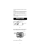
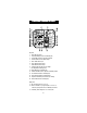
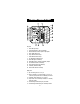
FRONT PANEL
Left panel
1. Alarm LED signal for pH
2. Liquid Crystal Display for pH and Conductivity
3. Alkaline feed LED and dial to adjust the pH setpoint
5. Alarm disable switch for pH
6. Slope calibration trimmer for pH
7. Offset calibration trimmer for pH
9. Two independent overdosage timers
10. Alarm LED signal for Conductivity
11. Bleed LED and dial to adjust the Conductivity setpoint
12. Zero calibration trimmer for Conductivity
13. Slope calibration trimmer for Conductivity
15. Conductivity Dead Band setting
16. Alarm disable switch for Conductivity
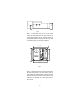
Right panel
17. pH alarm setting from 0.0 to 2.0 pH
18. Short the terminals if a pH ground probe is not in use, or
connect the ground probe wire to the Matching Pin terminal
19. Conductivity alarm setting from 0 to 2.0 mS/cm
20. Triple contact alarm in a Normally Closed (NC) or a Normally
Open (NO) position.
21. Powered dosage terminals (Relay) for pH correction
22. Powered dosage terminals (Relay) for Conductivity correction