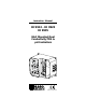
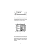
Instruction Manual HI 9913 - HI 9923 HI 9935 Wall Mounted Dual Conductivity/TDS & pH Controllers FE 5 SLOP E 0 ALAR M ON 1.5 ALAR 2 M 1 ALA ACID OFFS ET 0.5 1 0 pH ACID OFF mS ALK 2.5 2.0 pH 0 PROP ORTIO SE NAL SETT CONDS 90 INGS SET 5 ALAR M 7.5 1 EC MINU 10 TE TIMER S mS mS FERT ZERO CAL SLOP E CA L 0.5 1.5 2 4 0 0 pH HI 99 1 pH SET pH SET EC ALA FEE 2 3 ON ALAR M OFF 2.0 mS 0 PROP ORTIO NAL SE SETT COND 90 INGS S 2.5 1 5 SET 7.
Dear Customer, Thank you for choosing a Hanna Product. Please read this instruction manual carefully before using the instrument. This manual will provide you with the necessary information for a correct use of the instrument, as well as a more precise idea of its versatility. If you need more technical information, do not hesitate to e-mail us at tech@hannainst.com. These instruments are in compliance with the directives EN 50081-1, 50082-1 and 61010-1. TABLE OF CONTENTS PRELIMINARY EXAMINATION ..........
PRELIMINARY EXAMINATION Remove the instrument from the packing material and examine it carefully to make sure that no damage has occurred during shipping. If there is any noticeable damage, notify your Dealer. Note: Save all packing materials until you are sure that the instrument functions correctly. Any defective item must be returned in the original packaging together with the supplied accessories. IMPORTANT: 1. Read the instructions before using the instrument. 2.
The controllers come equipped with relays operating at a maximum of 2A (240V). They incorporate a triple contact alarm system. When activated, the alarm contacts will open or close, triggering the mechanism of your choice, whether a buzzer, light or any other electrical device. The controllers are housed in a rugged, modular, fiber-reinforced ABS housing. All models can be wired to work with 110/115V or 220/240V at 50/60 Hz power supplies.
3“ 75 mm 25 mm 1“ 96.9 mm 3.8“ Fig. 3 Figure 3 is a dimensioned, bottom view of the wall mounted controller. The modular design isolates the control circuitry from the contacts making it possible to make the connections and then close the compartment. Adjustments can then be made only in the control area, without having to open the contacts compartment. 6.9“ 174.8 mm 7.4“ 188.6 mm 227.8 mm 9“ 221.8 mm 8.7“ Fig. 4 Figure 4 is a dimensioned front view of the wall mounted controller.
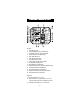
FUNCTIONAL DIAGRAM HI 9913 FRONT PANEL 1 17 18 2 19 3 HI 9913 4 5 6 7 8 1 pH 10 11 12 13 pH ALARM ACID FEED 0 SLOPE ALARM ACID 4 ON 7 SET OFF 0.5 0 2 mS 5 ALK 2.5 1.5 2 ALARM 1 6 5 OFFSET 2.0 0 pH SECONDS PROPORTIONAL SETTINGS 90 20 7.5 ALARM 0 9 2 pH 10 1 MINUTES TIMER 21 SET pH mS EC SLOPE CAL 23 ON ALARM 1 SET 2.5 1.5 2.0 0 90 mS SECONDS PROPORTIONAL SETTINGS 4 5 OFF 0 SET EC 3 2 ZERO CAL 22 FEED FERT mS 0.5 ALARM 7.
20. Triple contact alarm in a Normally Closed (NC) or a Normally Open (NO) position. 21. Powered dosage terminals (Relay) for pH correction 22. Powered dosage terminals (Relay) for EC correction 23. 110/115V or 220/240V power configuration 24. Incoming power terminals 25. Fuses BOTTOM VIEW 26 27 28 26. Female BNC connector for a combination pH electrode 27. 4-mm Banana socket for the pH ground probe 28.
Specifications RANGE HI 9913 0.00 to 14.00 pH and 0.00 to 10.00 mS/cm (EC) RESOLUTION ACCURACY (@20°C/68°F) 0.01 pH and 0.01 mS/cm ±0.02 pH and ±2% F. S. TYPICAL EMC DEVIATION ±0.1 pH and ±2% F. S. CALIBRATION Through "OFFSET" and "SLOPE" trimmers for pH, and “ZERO CAL” and “SLOPE CAL” for Conductivity (EC) SETPOINT RANGE From 4.0 to 7.0 pH and 1.0 to 4.0 mS/cm (EC) PROPORTIONAL CONTROL Two independent controls: pH from 0.0 to 2.0 and Conductivity (EC) from 0.0 to 2.
FUNCTIONAL DIAGRAM HI 9923 FRONT PANEL 1 17 18 2 19 3 5 6 pH pH 7 0 FEED SLOPE AUTO 2 ALARM 1 7.5 OFFSET 20 1 ALARM ALK 5 0 10 21 2 mS SET 9 45 MANUAL ALARM 10 22 90 1 MINUTES pH TIMER 11 12 pH HI 9923 mS mS SET pH ALARM BLEED ZERO CAL SLOPE CAL SET EC 23 4 3 2 13 5 AUTO 6 1 SET 45 MANUAL 15 0.50 0 24 90 1 MINUTES mS TIMER mS DEAD BAND 16 LINE 9 25 Left panel 1. Alarm LED signal for pH 2. Liquid Crystal Display for pH and Conductivity 3.
23. 110/115V or 220/240V power configuration 24. Incoming power terminals 25. Fuses BOTTOM VIEW 26 27 28 26. Female BNC connector for a combination pH electrode 27. 4-mm Banana socket for the pH ground probe 28. Female DIN connector for conductivity probe Unplug the instrument from the power supply before wiring or replacing the fuses.
Specifications RANGE RESOLUTION ACCURACY (@20°C/68°F) HI 9923 0.00 to 14.00 pH and 0.00 to 10.00 mS/cm (mmho/cm) 0.01 pH and 0.01 mS/cm (mmho/cm) ±0.02 pH and ±2% F. S. TYPICAL EMC DEVIATION ±0.1 pH and ±2% F. S. CALIBRATION Through "OFFSET" and "SLOPE" trimmers for pH, and “ZERO CAL” and “SLOPE CAL” for Conductivity SETPOINT RANGE DEAD BAND ALARM CONTACT PROBE DOSING TERMINALS POWER SUPPLY ENVIRONMENT WEIGHT ENCLOSURE CASE MATERIAL From 5.0 to 10.0 pH & 1.00 to 6.00 mS/cm (mmho/cm) From 0.0 to 0.
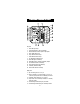
FUNCTIONAL DIAGRAM HI 9935 FRONT PANEL 1 17 18 2 19 3 6 pH 9 2 10 11 12 13 SLOPE 2.0 0 pH SECONDS PROPORTIONAL SETTINGS 0 2 ALARM 200 6 4 7 400 ppm SET 5 7.5 90 21 10 1 MINUTES TIMER SLOPE CAL SET pH ppm ALARM FERT FEED 1200 1500 ALARM 900 SET 1800 5 OFF 2.5 400 0 90 ppm SECONDS PROPORTIONAL SETTINGS 22 23 ON 300 20 ALARM SET EC ZERO CAL 0 FEED 2.5 1.5 TDS ppm 100 ACID 1 0 ALARM 0 ALARM ON OFF 0.5 pH 5 OFFSET 7 8 pH HI 9935 5 7.
21. 22. 23. 24. 25. Powered dosage terminals (Relay) for pH correction Powered dosage terminals (Relay) for TDS correction 110/115V or 220/240V power configuration Incoming power terminals Fuses BOTTOM VEW 26 27 28 26. Female BNC connector for a combination pH electrode 27. 4-mm Banana socket for the pH ground probe 28. Female DIN connector for TDS probe Unplug the instrument from the power supply before wiring or replacing the fuses.
Specifications HI 9935 0.00 to 14.00 pH and 0.00 to 1999 ppm (mg/L) RANGE RESOLUTION ACCURACY (@20°C/68°F) 0.01 pH and 1 ppm (mg/L) ±0.02 pH and ±2% F. S. TYPICAL EMC DEVIATION ±0.1 pH and ±2% F. S. CALIBRATION Through "OFFSET" and "SLOPE" trimmers for pH, and “ZERO CAL” and “SLOPE CAL” for TDS SETPOINT RANGE From 4.0 to 7.0 pH and 900 to 1800 ppm (mg/L) PROPORTIONAL CONTROL Two independent controls: pH from 0.0 to 2.0 and TDS from 0.
• Unscrew the 4 screws on the right hand panel and remove the cover and the gasket. Thread the wires through the access ports on the right hand side of the controllers. • Before connecting the controller to the mains, wire the controller completely and make all the connections for pumps, valves, alarm, probe, set the alarm threshold and adjust the settings. Upon completion replace the cover cover. Only then connect the controller to the power supply.
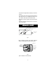
CONDUCTIVITY/TDS PROBE CONNECTION • Attach the conductivity/TDS probe (HI 3002, HI 3001D or HI 7638) to the DIN socket located on the bottom of the casing. Align the guide on the connector with the socket, push the connector in and tighten the retainer ring. (HI 3002 is more suitable for direct immersion in the tank, vat or pipes. HI 3001D can be mounted directly into a pipe and HI 7638 is recommended for high temperature and pressure applications).
• The operator can similarly select an pH pH 1 1 alarm threshold of 0.0 to 2.0 mS/cm (HI 9913 and HI 9923) or 0 to 400 0 ppm (HI 9935) by turning the alarm 0 ALARM 2 ALARM 2 200 1 knob (see 19 - Functional Diagram). If the conductivity/TDS measurements ex400 0 2 0 ppm ceed the setpoint (HI 9913 and HI mS 9935) or the conductivity falls below the setpoint (HI 9923) by a margin greater than the userselectable alarm threshold, the alarm terminal is activated.
• The alarm is also activated if one or both of the independent maximum dosage times are exceeded. The maximum time that the relay contacts remain active continuously (max. dosage time) can be set from 1 to 10 minutes for HI 9913 and HI 9935 and 1 to 90 minutes for HI 9923. • Once in an alarm condition, the contact remains activated until the switch is put in the manual position or the measurements return to normal values. 5 2.5 7.
NORMAL OPERATION & MEASUREMENT Make sure that the controller has been properly calibrated before commencing and that the pH and conductivity/TDS setpoints have been adjusted (see following pages). The pH electrode, conductivity/TDS probe and any ground probe must be properly connected and wired to the controller (see preceding pages). The conductivity/TDS probe’s protective sleeve must not be removed and the holes on the sleeve should be near the top (the cable end).
pH CALIBRATION 4 cm (1½") Make sure that the pH electrode and any ground probe have been properly connected and wired to the controller (see preceding pages) and that the meter is plugged to the mains. Calibration should be performed at a temperature similar to that of the liquid to be monitored. Use a Checktemp (or an accurate thermometer) as reference. Remove the electrode cap if it is still on the electrode.
• If the temperature of the buffer solution is not 25°C (77°F), refer to the chart at the end of the manual for the appropriate buffer value at a given temperature and adjust the trimmer accordingly. SLOPE ADJUSTMENT: 4 cm (1½") • Rinse the electrode (and ground probe) thoroughly with water and immerse the bottom 4 cm (1.5”) in a pH 10.01 (HI 7010) or a pH 4.01 (HI 7004) buffer solution.
ments are in the 1.2 to 2.5 EC range. Similarly, utilize HI 7039L with a value of 5.00 mS/cm at 25 °C if controlling your process with HI 9923 and HI 70442L with a value of 1500 ppm (mg/L) value if working with HI 9935. • Immerse the probe in the beaker ensuring that the holes on the sleeve of the probe are completely covered. • Stir the probe and tap it gently on the bottom of the beaker to ensure that any air bubbles trapped inside the sleeve escape.
ADJUSTEMENT OF SETPOINTS Make sure that the pH electrode, conductivity/TDS probe and any ground probe have been properly installed and calibrated (see the preceding pages). FOR pH Simply turn the pH ACID FEED or ALK FEED dial (see 3 - Functional Diagram). The desired value can be chosen between 4 and 7 pH for HI 9913 and HI 9935, and 5 and 10 pH for HI 9923. ACID FEED 6 5 4 DOSING DIRECTION 7 SET The dosing terminals of HI 9935 are activated when the pH value exceeds the setpoint.
PROPORTIONAL CONTROL (HI 9913 & HI 9935) In order to optimize the controlling process and reduce the amount of chemicals and fertilizers used, it is recommended to use a proportional dosage appropriate for the system. HI 9913 and HI 9935 allow 0.5 1.5 for a proportional band (delta) 2.0 0 90 0 of 0 to 2.0 pH. They also pH SECONDS PROPORTIONAL SETTINGS allow for of proportional band of 0 to 2.0 mS/cm and 0 to 0.5 1.5 400 ppm for conductivity (EC) 0 2.0 0 90 and TDS, respectively.
e.g. EC proportional control for HI 9913 Setpoint = 2.20 mS/cm (EC) Measured value = 1.45 mS/cm Delta = 2.20 - 1.45 = 0.75 mS/cm Proportional settings = EC set to 1 and time cycle to 60 seconds The controller will be dosing 0.5 1.5 fertilizers to increase the EC to 0 2.0 0 90 the desired limit. Since it is mS SECONDS PROPORTIONAL SETTINGS 0.75/1 = 75% away from the ideal setting, it will keep the D mS dosing really activated for 75% 1.00 of the time over the predeter0.75 mined 60 seconds.
e.g. HI 9935 proportional control Setpoint = 1600 ppm (TDS) Measured value = 1550 ppm Delta = 1600 - 1550 = 50 ppm Proportional settings = ppm set to 200 and time cycle to 60 seconds The controller will be dosing fertil- D ppm izers to reach the desired value. Since it is 50/200 = 25% away 200 from the ideal setting, it will 150 keep the dosing really activated 100 for 25% of the time over the 50 predetermined 60 seconds.
With HI 9913 and HI 9935, the cycles are selectable from 1 to 10 minutes for both pH and EC/TDS. For HI 9923 instead, the timers can be set from 1 to 90 minutes to allow for proper blow down of the boiler or cooling tower. Should this period elapse, the alarm terminals are activated (and dosage terminals are disactivated). This is to ensure that fertilizers or chemicals have not run out or pumps or electrovalves have not ceased to function properly. 5 2.5 7.
pH ELECTRODE CONDITIONING & MAINTENANCE PREPARATION Remove the protective cap. DO NOT BE ALARMED IF ANY SALT DEPOSITS ARE PRESENT. This is normal with electrodes and they will disappear when rinsed with water. During transport tiny bubbles of air may have formed inside the glass bulb (membrane). shake down the electrode as you would do with a glass thermometer to remove these bubbles. If the bulb and/or junction are dry, soak the electrode in a HI 70300 Storage Solution overnight.
TROUBLESHOOTING Evaluate your electrode performance based on the following. • Noise (Readings fluctuate up and down) could be due to clogged/dirty junction: Refer to the Cleaning Procedure above. • Dry Membrane/Junction: Soak in Storage Solution HI 70300 overnight. Check to make sure the installation is such as to create a well for the electrode bulb to constantly remain moist. • Low Slope: Refer to the cleaning procedure above.
CLEANING PROCEDURE Remove the sleeve and soak the probe in a Hanna HI 7061 General Cleaning Solution for 1 hour. If the probe has been left in highly concentrated fertilizer solution and does not seem to become clean, repeat the cleaning procedure. The rings can also be cleaned with a cloth. Make sure that the cloth is made of a soft and non-abrasive material and does not scratch the rings. IMPORTANT: After performing the cleaning procedure rinse the probe thoroughly with distilled or tap water.
The conventional electrodes may be used for indoor applications but the cable length should not exceed 10 m (33'). MEDIUM DISTANCE, INDOOR/OUTDOOR INSTALLATION When an outdoor installation is required, it is normally necessary to install a transmitter to obtain accurate readings at distances from 10 to 50 m (33-165'). Since the introduction of AmpHel electrodes these distances are no longer a problem. You can now connect your meter directly to an AmpHel electrode, saving the cost of a transmitter.
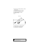
HI 3002 FOR IN-LINE INSTALLATION The drawing illustrates the ideal installation system since the stream pressure in the pipe forces the air bubbles out automatically. HI 3001D illustrated preaviously can also be mounted in this fashion. However the longer HI 3002 stem of HI 3002 facilitates an easier > 1/2“ GAS escape route for any air bubbles. HI 3002 comes with external 1/2” NPT and thread 60 mm (2.4”) immersion level.
ACCESSORIES pH ELECTRODES HI 1002/3 HI 1003/3 HI 2911B/5 HI 1090B/5 Double Teflon junction with external threads Double Teflon junction with matching pin Preamplified, double Teflon junction Glass double junction with external threads EC/TDS PROBE 1/2” NPT platinum 20 mm (0.8”) long, 4-ring probe with temperature sensor and external threads for pipes HI 3002 1/2” NPT platinum 60 mm (2.4”) 4-ring probe with temperature sensor and external threads for pipes and tanks HI 7638 3/8” NPT platinum 60 mm (2.
OTHER ACCESSORIES BL PUMPS ChecktempC ChecktempF HI 6050 HI 6051 HI 6054B HI 8427 HI 931001 Dosing pumps (several models are available with flow rates from 1.5 to 18.3 lph / 0.4 to 4.8 gph) Pocket-size thermometer (range -50.0 to 150.0°C) Pocket-size thermometer (range -58.0 to 302.0°F) Submersible pH electrode holder (605 mm/23.8" total length) Submersible pH electrode holder (1105 mm/43.
CE DECLARATION OF CONFORMITY DECLARATION OF CONFORMITY We Hanna Instruments Srl V.le delle industrie 12 35010 Ronchi di Villafranca (PD) ITALY herewith certify that the wall-mounted instrument: HI 9913 HI 9923 HI 9935 has been tested and found to be in compliance with the following regulations: IEC 801-2 IEC 801-3 IEC 801-4 EN 55022 EN 61010-1 Electrostatic Discharge RF Radiated Fast Transient Radiated, Class B User Safety Requirement Date of Issue: 07-06-1999 D.
HANNA LITERATURE Hanna publishes a wide range of catalogs and handbooks for an equally wide range of applications. The reference literature currently covers areas such as: • Water Treatment • Process • Swimming Pools • Agriculture • Food • Laboratory • Thermometry MAN9913 10/99 For these and other catalogs, handbooks and leaflets, contact your dealer or the Hanna Customer Service Center nearest to you. To find the Hanna Office in your vicinity, check our home page at www.hannainst.com.