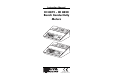
Instruction Manual HI 8819 - HI 8820 Bench Conductivity Meters HI 88 19 ON OFF COND TEMP Standa rd Standa Conduc tivity rd at 25 HI 70 °C Cond 33 uctivity HI 70 HI 70 31 90 30 1413 µS HI 70 µS 34 12,88 0 µS 80,00 0 µS 199.9 µS 19.9 mS 9 1999 µS 99.9 mS TEMPE RATURE HI 88 20 ON OFF Standa rd Standa Conductiv ity at rd 25°C HI 70 Cond 33 uctivity HI 70 31 90 µS HI 70 199.9 30 1413 HI 70 µS µS 12,88 34 0 µS 80,00 0 µS 19.99 mS 99.9 mS 1999 µS 0.5 1 1.
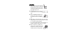
Dear Customer, Thank you for choosing a Hanna Instruments Product. Please read this instruction manual carefully before using the instrument. This manual will provide you with all the necessary information for the correct use of the instrument, as well as a precise idea of its versatility in a wide range of applications. These instruments are in compliance with CSA, UL and (EN 50081-1 and EN 50082-1) directives. TABLE OF CONTENTS PRELIMINARY EXAMINATION .....................................................
PRELIMINARY EXAMINATION Remove the instrument from the packing material and examine it to make sure that no damage has occurred during shipping. If there is any damage, notify your Dealer. Each meter comes supplied with a conductivity probe (HI7685 for HI8819 or HI7687 for HI8820), a voltage adapter, a dust cover and an instruction manual. Note:: Save all packing material until you are sure that the instrument functions correctly.
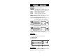
KEYBOARD & REAR PANEL KEYBOARD: ON/OFF To switch the instrument ON or OFF COND/TEMP To select the display of conductivity readings or temperature settings for compensation (for HI8819 only) 199.9 µS To select the range 0.0 to 199.9µS/cm 1999 µS To select the range 0 to 1999µS/cm 19.99 mS To select the range 0.00 to 19.99 mS/cm 99.9 mS To select the range 0.0 to 99.
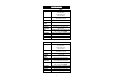
SPECIFICATIONS Range Resolution Accuracy Typical EMC Deviation Calibration Temperature Compensation Probe Power Supply Environment Dimensions Weight Range Resolution Accuracy Typical EMC Deviation Calibration Temperature Compensation Probe Power Supply Environment Dimensions Weight HI8819 0.0 to 199.9 µS/cm 0 to 1999 µS/cm 0.00 to 19.99 mS/cm 0.0 to 99.9 mS/cm 0.1 µS/cm; 1 µS/cm 0.01 mS/cm; 0.
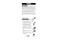
CONDUCTIVITY MEASUREMENTS Make sure that the instrument has been calibrated before taking conductivity measurements (see page 8 for calibration procedure). Connect the probe to the back of the meter and switch the instrument on by pressing the ON/OFF key. If possible, to minimize any EMC interferences, use plastic beakers for the solutions. FOR HI8819: • Immerse the probe in the solution submerging the holes of the sleeve (0.5 cm below).
FOR HI8820: • Immerse the probe in the solution submerging the holes of the sleeve (0.5 cm below). Tap the probe lightly on the bottom of the recipient to remove any air bubbles which may have being trapped inside the sleeve. • If the display shows only a "1", there is an over-range condition. Select the next higher range. • Adjust the "TEMPERATURE COEFFICIENT" knob to the value of the solution. See page 15 for the procedure to select the correct coefficient value.
CALIBRATION INITIAL PREPARATION HI 703 0 If you are measuring in the mS ranges, calibrate the meter using HI7030 (or HI8030) conductivity solution (12.88 mS @ 25°C) or HI7034 (or HI8034) conductivity solution (80 mS @ 25°C). Choose a solution with a conductivity value close to the solution to be measured.
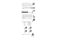
• Press the COND/TEMP key to display conductivity readings and select the appropriate conductivity range e.g. "19.99 mS" for HI7030/HI8030, "99.9 mS" for HI7034/HI8034, "1999µS" for HI7031/HI8031, "199.9 µS" for HI7033/HI8033. • Using a small screwdriver adjust the trimmer on the rear panel until the display shows the conductivity reading at the temperature of the solution noted earlier (see the mS conductivity vs. temperature chart on page 13) e.g. "11.19 mS".
0 703 HI • Press the COND/TEMP key to display conductivity. • The display should read the conductivity of the calibrating solution at the reference temperature. E.g. using HI7030/HI8030 with a solution at 18°C, the reading will be "12.88 mS". PROCEDURE FOR HI8820: • Pour a small quantity of the conductivity solution into a plastic beaker. • Immerse the conductivity probe in the solution submerging the holes of the sleeve (0.5 cm below). Make sure that no air bubbles are trapped inside the glass sleeve.
• Using a small screwdriver adjust the trimmer on the rear panel until the display shows the conductivity reading at 25°C (77°F), e.g.: "12.88 mS" for HI7030/HI8030, "80.00 mS" for HI7034/HI8034, "1413 µS" for HI7031/HI8031, "84 µS" for HI7033/HI8033. CONDUCTIVITY ELECTRODE CAL DC POWER 12V to 20V + If you are using a different reference temperature, refer to the conductivity vs temperature charts on page 12 for the appropriate conductivity reading at the reference temperature. E.g.
CONDUCTIVITY VERSUS TEMPERATURE CHART The conductivity of an aqueous solution is the measure of its ability to carry an electrical current by means of ionic motion. The conductivity invariably increases with increasing temperature. It is affected by the type and number of ions in the solution and by the viscosity of the solution itself. Both parameters are temperature dependent.
TEMPERATURE COMPENSATION The conductivity of an aqueous solution is the measure of its ability to carry an electrical current by means of ionic motion. The conductivity invariably increases with increasing temperature. It is affected by the type and number of ions in the solution and by the viscosity of the solution itself. Both parameters are temperature dependent.
DETERMINATION OF THE TEMPERATURE COEFFICIENT OF A SOLUTION (for HI8820 only) Follow the procedure described below: 1) Immerse the probe into a sample of the solution and adjust the knob to 0% (i.e. no compensation). 2) Condition the sample and probe at 25°C and note the conductivity reading C25. 3) Condition the sample and probe to a temperature t°C which is approximately 5°C to 10°C different from 25°C and note the conductivity reading Ct.
PROBE MAINTENANCE Rinse the probe with tap water after every series of measurements. If a more thorough cleaning is required, remove the glass sleeve and clean the probe with a cloth or a nonabrasive detergent. After cleaning the probe, re-calibrate the instrument. The four ring platinum probe body and sleeve are in glass. For this reason great care while handling the probe must be taken.
ACCESSORIES CONDUCTIVITY BUFFER SOLUTIONS: HI 7030L HI 7030M HI 7031L HI 7031M HI 7033L HI 7033M HI 7034L HI 7034M HI 7035L HI 7035M HI 7039L HI 7039M 12880 µS/cm (µmho/cm), 460mL 12880 µS/cm (µmho/cm), 230mL 1413 µS/cm (µmho/cm), 460mL 1413 µS/cm (µmho/cm), 230mL 84 µS/cm (µmho/cm), 460 mL 84 µS/cm (µmho/cm), 230 mL 80000 µS/cm (µmho/cm), 460mL 80000 µS/cm (µmho/cm), 230mL 111800 µS/cm (µmho/cm), 460mL 111800 µS/cm (µmho/cm), 230mL 5000 µS/cm (µmho/cm), 460mL 5000 µS/cm (µmho/cm), 230mL CONDUCTIVITY BUFF
OTHER ACCESSORIES: CHECKTEMPC HI710005 HI710006 Electronic thermometer (range: -50.0 to 150.
WARRANTY All Hanna Instruments meters are guaranteed for two years against defects in workmanship and materials when used for their intended purpose and maintained according to instructions. The electrodes and the probes are guaranteed for a period of six months. This warranty is limited to repair or replacement free of charge. Damage due to accident, misuse, tampering or lack of prescribed maintenance are not covered. If service is required, contact the dealer from whom you purchased the instrument.
CE DECLARATION OF CONFORMITY Recommendations for Users Before using these products, make sure that they are entirely suitable for the environment in which they are used. Operation of these instruments in residential area could cause unacceptable interferences to radio and TV equipments, requiring the operator to take all necessary steps to correct interferences. The metal band at the end of the sensor is sensitive to electrostatic discharges. Avoid touching this metal band at all times.
PRINTED IN PORTUGAL MANBNCONR2 01/99 h t t p : / / w w w . h a n n a i n s t .