HI 21/HI 22 Series Wall-mounted, Microprocessor-based Process pH/mV Meters Instruction Manual
Dear Customer, Thank you for choosing a Hanna Product. Please read this instruction manual carefully before using the instrument. It will provide you with the necessary information for the correct use of the instrument, as well as a precise idea of its versatility. If you need additional technical information, do not hesitate to e-mail us at tech@hannainst.com tech@hannainst.com. These instruments are in compliance with the directives. TABLE OF CONTENTS PRELIMINARY EXAMINATION . . . . . . . . . . . . . .
PRELIMINARY EXAMINATION Remove the instrument from the packing material and examine it carefully to make sure that no damage has occurred during shipping. If there is any noticeable damage, notify your Dealer or the nearest Hanna Customer Service Center immediately. Note Save all packing materials until you are sure that the instrument functions correctly. Any damaged or defective items must be returned in their original packing materials together with the supplied accessories.
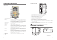
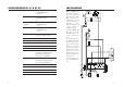
FUNCTIONAL DESCRIPTION CONNECTIONS PANEL FRONT PANEL 1. Liquid Crystal Display 2. LCD key exits from setup and calibration modes and reverts back to normal mode (in idle or control phases with the measurement on the display). In HI 21 series, during pH calibration, alternately displays pH buffer value or current temperature 3. CAL DATA key last calibration data viewing (enters and exits) 4. SETUP key enters setup mode 5. CAL key initiates and exits calibration mode 6.
SPECIFICATIONS HI 21 & HI 22 Range 0.00 to 14.00 pH (HI 21 Series only) ±2000 mV (HI 22 Series only) -9.9 to 120.0 °C Resolution 0.01 pH (HI 21 Series only) 1 mV (HI 22 Series only) 0.1 °C Accuracy ±0.02 pH (HI 21 Series only) ±2 mV (HI 22 Series only) ±0.5 °C (@20°C/68°F) 8 Typical EMC Deviation ±0.05 pH (HI 21 Series only) ±4 mV (HI 22 Series only) ±1.
• Power Supply: Connect a 3-wire power cable to the terminal strip, while paying attention to the correct line (L), earth (PE) and neutral (N) terminal connections. Power: 115VAC - 100 mA / 230VAC - 50 mA. Line Contact: fused inside 400 mA. PE must be connected to ground; leakage current 1 mA. • Electrode: Connect the pH or ORP electrode to the BNC socket (#10 at page 6).
• Then confirm the displayed digit with ð and move to the next one. • When the whole password has been inserted, press CFM to confirm it. Note The default password is set at “0000”. • The LCD will display “SET” on the upper part and “c.00” on the lower, allowing the user to edit setup parameters (see table below). • After confirmation, the selected parameter is displayed. The user can scroll through the parameters by pressing CFM.
Code Valid Values Default PW Code Valid Values Default PW 23* Relay 2 hysteresis (H2) 0.00 to 14.00 pH 0 to 4000 mV 1 pH 50 mV no 60 Current day 01 to 31 from RTC no 61 Current month 01 to 12 from RTC no 24* Relay 2 deviation (D2) 0.50 to 14.00 pH 25 to 4000 mV 1 pH 50 mV no 62 Current year 1997 to 9999 from RTC no 63 Current time 00:00 to 23:59 from RTC no 25* Relay 2 reset time (HI 21523 only) 0.1 to 999.9 minutes 999.
If M1 = 2 and M2 = 3 then S1+H1LA, HA>S2+D2; If M1 = 4 and M2 = 1 then S1LA, HA>S2; If M1 = 1 and M2 = 4 then S1–H1>S2, S2–D2>LA, HA>S1; If M1 = 3 and M2 = 4 then S1>S2, S2–D2>LA, HA>S1+D1; If M1 = 4 and M2 = 3 then S2>S1, S1–D1>LA, HA>S2+D2; For HI 21523 only: If M1 = 1 then S1+D1LA; where the minimum deviation (D1 or D2) is 0.5 pH (for HI 21) or 25 mV (for HI 22).
dosage, if available). An upper boundary is imposed for acid/base dosage time when relays are energized continuously, i.e. when relay works in ON/OFF mode or in PID mode but in the latter case only if the relay is always ON. This parameter can be set through setup procedure. When the maximum boundary is reached, an alarm is generated; device stays in alarm condition until relay is de-energized.
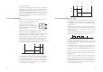
An example of how the response overshoot can be improved with a proper rate action setting is depicted in the following graphic. In HI 21 and HI 22 the proportional action is set directly as “Deviation” in pH and mV units respectively. Relation between Deviation (D) and PB is: D = Range * PB/100 Each setpoint has a selectable proportional band: PB1 for setpoint1 and PB2 for setpoint2.
1. Starting from a solution with a pH or mV value different from the dosed liquid (at least a 3 pH or 150 mV difference) turn on the dosing device at its maximum capacity without the controller in the loop (open loop process). Note the starting time. 2. After some delay the pH or mV starts to vary. After more delay, the pH or mV will reach a maximum rate of change (slope). Note the time that this maximum slope occurs and the pH or mV value at which it occurs. Note the maximum slope in pH or mV per minute.
This is an important feature since with most meters the alarm terminals close only when an abnormal situation arises, however, due to line interruption, no alarm is sounded, causing extensive damage. On the other hand, software is employed to set off the alarm in abnormal circumstances, for example, if the dosing terminals are closed for too long a period. In both cases, the red LED’s will also provide a visual warning signal.
These values can be changed by the user to have the analog output matching a different pH range, for example, 4 mA = 3.00 pH and 20 mA = 5.00 pH. To change the default values, the setup mode must be entered. Setup codes for changing the analog output minimum and maximum are 41 or 42, respectively. For the exact procedure, refer to the setup mode section in the manual. ANALOG OUTPUT All models HI 21XY1, HI 21XY3 and HI 22XY1 are provided with the analog output feature.
RS485 COMMUNICATION HI 21XY2, HI 21XY3 and HI 22XY2 are provided with an RS485 port. RS485 standard is a digital transmission method that allows long lines connections. Its current-loop system makes this standard suitable for data transmission in noisy environments. Data transmission from the instrument to the PC is possible with the HI 92500 Windows® compatible application software offered by Hanna Instruments.
As additional feature, the controller is also provided with two pins (5V and 0V) in order to apply the Fail Safe Open Line protection method. To avoid erroneous readings in Open-Line conditions, pullup and pull-down resistors should be connected as shown.
TMR null Request temperature reading Note If the controller is not in control or idle mode and the temperature reading is requested through the TMR command, the controller answers with the last acquired reading when it was in control or idle mode. Note After a recognized PWD command is received, the controller allows a maximum of 1 minute without receiving data, after which it locks again and a new PWD command is needed to perform password protected operations.
HI 22: 1
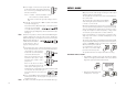
For accurate calibration, use two beakers for each buffer solution, the first one for rinsing the electrode, the second one for calibration. By doing this, contamination between the buffers is minimized. RINSE CALIBRATION HI 7007 HI 7007 To obtain accurate readings, use pH 7.01 and pH 4.01 if you measure acidic samples, or pH 7.01 and pH 10.01 for alkaline measurements or perform a 3-point calibration for the entire range.
Two-point Calibration • Proceed as described above for one-point calibration, using pH 7.01 as the first point, but do not quit calibration by pressing CAL at the end. Note Three-point Calibration • Proceed as described above but do not quit calibration by pressing CAL. Note The meter will automatically skip the buffer that was used for the first calibration to prevent errors.
CALIBRATION WITH MANUAL TEMPERATURE COMPENSATION • Enter the calibration procedure and press LCD to display the temperature on the secondary LCD. • Unplug any temperature probe that may be attached to the meter. The "°C" symbol will flash. • Note the temperature of the buffer solutions with a ChecktempC or another accurate thermometer with a resolution of 0.1°C. • Use ñ or ò to manually adjust the display reading to the value of the reference thermometer (e.g. 20°C).
OFFSET AND SLOPE DIRECT SELECTION (HI 21523 ONLY) Whenever the pH electrode offset and slope parameters are known, it is possible to directly calibrate the meter entering the electrode parameters. • Press the “CAL DATA” and then “SETUP”. The LCD will show the default offset of -5.0 mV. • Using the ñ, ò and ð enter the electrode offset parameter (the value must be between -100 and +100 mV). • Confirm the value by pressing CFM. If offset is invalid the “WRONG” indicator will blink on the LCD.
• When the reading has stabilized at a point near the first calibration point, CAL will stop blinking and an intermittent CFM icon will prompt the user to confirm the first calibration. • If the display stabilizes at a value significantly different from the first setpoint, an intermittent WRONG icon will prompt the user to check and adjust the simulator and start again. • After pressing CFM the unit will switch to the second calibration point at 350 mV.
°C • Immerse the temperature probe in the second beaker as near to the Checktemp as possible and repeat the above procedure. • Press CFM to confirm the parameter that stops blinking on the primary display. The secondary display shows the multimeter or HI 931002 input value as the interval lower limit. 50 °C (122 °F) Calibration procedure may be interrupted by pressing CAL again at any time.
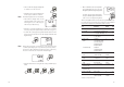
LAST CALIBRATION DATA The meter stores the following information about last calibration in the EEPROM: • Date • Time • Offset in mV (for HI 21 only) • Up to two slopes (for HI 21 only) • Up to three buffers While displaying this data, the pH controller remains in control mode. The procedure below indicates the flow for a three-point calibration. The sequence will vary if fewer calibration points are used (e.g.
• Press ñ or ð again to view the second memorized buffer at the time of last calibration. The secondary display will show "BUF2" to indicate second buffer. • Press ñ or ð again to view the third memorized buffer at the time of last calibration. The secondary display will show "BUF3" to indicate third buffer. • Press ñ or ð again to return to the first CAL DATA display (date) at the time of last calibration.
The error detection for dead loops is performed by watchdog (see below). You can use special setup codes, perform selftest procedures for LCD, keyboard, EEPROM, relays and LEDs, watchdog. The operation of these functions is outlined in the setup section. The selftest procedures are described in detail in the following subsections. FAULT CONDITIONS AND SELFTEST PROCEDURES The fault conditions below may be detected by the software: • EEPROM data error; • I2C internal bus failure; • code dead loop.
The colon is a useful indicator for the correct position of squares. Note RELAYS AND LEDS Relays and LEDs selftests are executed as follows: First all of the relays and LEDs are switched off, then they are switched on one at a time for a few seconds and cyclically. User can interrupt the otherwise endless cycle, as indicated by the scrolling message, by pressing a key. A maximum of two keys may be pressed simultaneously to be properly recognized.
pH VALUES AT VARIOUS TEMPERATURES ELECTRODE CONDITIONING AND MAINTENANCE Temperature has a significant effect on pH. The calibration buffer solutions are effected by temperature changes to a lesser degree than normal solutions. For manual temperature calibration please refer to the following chart: TEMP °C °F 4.01 pH VALUES 7.01 10.01 0 32 4.01 7.13 10.32 5 41 4.00 7.10 10.24 10 50 4.00 7.07 10.18 15 59 4.00 7.04 10.12 20 68 4.00 7.03 10.06 25 77 4.01 7.01 10.
If the bulb and/or junction are dry, soak the electrode in HI 70300 Storage Solution for at least one hour. For refillable electrodes**: If the refill solution (electrolyte) is more than 2½ cm (1") below the fill hole, add HI 7082 3.5M KCl Electrolyte Solution for double junction or HI 7071 3.5M KCl+AgCl Electrolyte Solution for single junction electrodes. For AmpHel® electrodes: If the electrode does not respond to pH changes, the battery is run down and the electrode should be replaced.
(replace the electrode if cracks are found). - Make sure cable and connections are not damaged nor lying in a pool of water or solution. • Slow Response/Excessive Drift: Soak the tip in Hanna Solution HI 7061 for 30 minutes, rinse thoroughly in distilled water and then follow the Cleaning Procedure above. • For ORP Electrodes: polish the metal tip with a lightly abrasive paper (paying attention not to scratch the surface) and wash thoroughly with water.
Note 62 pH mV pH mV pH mV pH mV pH mV ACCESSORIES 0 990 1 920 2 860 3 800 4 740 5 680 6 640 7 580 8 520 9 460 10 400 11 340 12 280 13 220 14 160 pH CALIBRATION SOLUTIONS HI 7004M pH 4.01 Buffer Solution, 230 mL HI 7004L pH 4.01 Buffer Solution, 460 mL HI 7004/L pH 4.01 Buffer Solution, 1 L HI 7007M pH 7.01 Buffer Solution, 230 mL HI 7007L pH 7.01 Buffer Solution, 460 mL HI 7007/L pH 7.01 Buffer Solution, 1 L HI 7010M pH 10.01 Buffer Solution, 230 mL HI 7010L pH 10.
RECOMMENDED pH ELECTRODES (All electrodes gel-filled and with ceramic junction unless otherwise indicated). HI 1090T Screw connector, external PG13.5 thread, double junction, glass-body, polymer filled HI 1210T HI 1211T HI 2910B/5 HI 2911B/5 HI 1090B/5 HI 1210B/5 Screw connector, external PG13.5 thread, double junction, Ultem®-body; cloth junction (HI 1210T); Teflon® junction, polymer-filled (HI 1211T) PLATINUM ORP ELECTRODES HI 3090T Screw connector, external PG13.
ORP ELECTRODES ½‘’ thread, double Teflon® junction, polymer filled, max operating pressure of 6 bar (87 psi) HI 3210B/5 BNC connector, 5 m (16.5') cable, double junction, Pt, Ultem®-body, Teflon® junction, polymer-filled PLATINUM ELECTRODES GOLD ORP ELECTRODES HI 4932B/5 BNC connector, 5 m (16.5') cable, double junction, Au, Ultem®-body with built-in amplifier and external thread Matching Pin Amplifier Connector Cable HI 2002/3 NO NO BNC 3 m (10’) HI 2002/5 NO NO BNC 5 m (16.
OTHER ACCESSORIES WARRANTY BL PUMPS Dosing Pumps with Flow Rate from 1.5 to 20 LPH ChecktempC ChecktempF HI 6050 & HI 6051 HI 6054 & HI 6057 HI 778P HI 7871 & HI 7873 HI 8427 HI 8614 HI 8614L HI 8615 HI 8615L HI 92500 HI 931001 HI 931002 Stick Thermometer (range -50.0 to 150.0°C) Stick Thermometer (range -58.
CE DECLARATION OF CONFORMITY HANNA LITERATURE Hanna publishes a wide range of catalogs and handbooks for an equally wide range of applications. The reference literature currently covers areas such as: • • • • • • • Water Treatment Process Swimming Pools Agriculture Food Laboratory Thermometry and many others. New reference material is constantly being added to the library. For these and others catalogs, handbooks and leaflets, contact your dealer or the Hanna Customer Service Center nearest to you.
MAN21R1 10/02 w 72 w w . h a n n a i n s t .