
User Guide

76
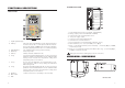
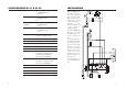
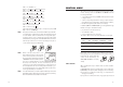
MECHANICAL DIMENSIONS
FRONT VIEW BOTTOM VIEW
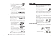
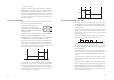
CONNECTIONS PANEL
1. 4-pin RS485 terminal (not for HI 21XY1 and HI 22XY1)
2. Analog output (not for HI 21XY2 and HI 22XY2)
3. Connections for Pt 100 temperature sensor
4. ±5V power supply output
5. Connection for Potential Matching Pin
6. Connection for electrode reference
7. Power supply input (1 Potential Earth, 2 Neutral, 3 Line)
8. Alarm terminal (1 F.S. Closed, 2 COM, 3 F.S. Open)
9. Relay 1 - first dosing terminal (not for HI 21523) - (1 Normally Open, 2 COM,
3 Normally Closed)
10. Relay 2 - second dosing terminal (HI 212XY models only) - (1 Normally Open,
2 COM, 3 Normally Closed)
Unplug the meter before starting any electrical connections.
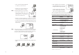
FUNCTIONAL DESCRIPTION
FRONT PANEL
1. Liquid Crystal Display
2. LCD key exits from setup and calibration modes and reverts back to
normal mode (in idle or control phases with the measure-
ment on the display). In HI 21 series, during pH calibration,
alternately displays pH buffer value or current temperature
3. CAL DATA key last calibration data viewing (enters and exits)
4. SETUP key enters setup mode
5. CAL key initiates and exits calibration mode
6. ñ key increases the blinking digit/letter by one when selecting a
parameter. Advances forward while in last calibration data
viewing mode. Increases the temperature setting when
temperature probe is not inserted
7. ð key moves to the next digit/letter (circular buffer) when select-
ing a parameter. Same as ñ key during last calibration
data viewing mode
8. ò key decreases the blinking digit/letter by one when selecting a
parameter. Reverts backward while in last calibration data
viewing mode. Decreases the temperature setting when
temperature probe is not inserted
9. CFM key confirms current choice (and skips to the next item)
10. BNC Socket
11. LEDs