Instruction Manual HI 2222 pH/mV/ºC Bench Meter with Calibration Check w w w. h a n n a i n s t .
Dear Customer, Thank you for choosing a Hanna Instruments product. Please read this instruction manual carefully before using this instrument. This manual will provide you with the necessary information for correct use of this instrument, as well as a precise idea of its versatility. If you need additional technical information, do not hesitate to e-mail us at tech@hannainst.com.
PRELIMINARY EXAMINATION Remove the instrument from the packing material and examine it carefully to make sure that no damage has occurred during shipping. If there is any damage, notify your Dealer or the nearest Hanna Customer Service Center. Each instrument is supplied complete with: • HI 1048P Glass-body Combination pH Electrode with 1 m (3.3 “) cable • HI 7662 Temperature Probe • HI 76404N Electrode Holder • pH 3.00 & 7.
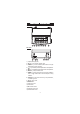
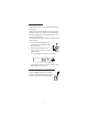
FUNCTIONAL DESCRIPTION Front Panel Rear Panel 1) Liquid Crystal Display (LCD). 2) CAL key, to enter and exit calibration mode. 3) CFM/GLP key, to confirm calibration, different values or to display Good Laboratory Practice information. 4) ºC key, to manually increase temperature value or other parameters. 5) ºC key, to manually decrease temperature value or other parameters. 6) SETUP key, to enter/exit SETUP mode.
HI 2222 SPECIFICATIONS –2.00 to 16.00 pH ±699.9 mV ±2000 mV Range –20.0 to 120.0 °C 0.01 pH 0.1 mV (±699.9 mV) 1 mV (±2000 mV) Resolution 0.1 °C ±0.01 pH Accuracy @ 20 °C/68 °F ±0.2 mV (±699.9 mV) ±1 mV (±2000 mV) ±0.2 °C excluding probe error Calibration Check Yes Computer Interface Opto-isolated USB pH Calibration Up to 2 points, 7 buffers available (1.68, 3.00, 6.86, 7.01, 9.18, 10.01, 12.45) Logging 100 points Temperature Compensation pH Electrode Manual or Automatic from: –20.0 to 120.
OPERATIONAL GUIDE POWER CONNECTION Plug the 12 VDC adapter into the power supply socket. Notes: • These instruments use non volatile memory to retain the pH, mV, temperature calibrations and all other settings, even when unplugged. • Make sure a fuse protects the mains line. ELECTRODE AND PROBE CONNECTIONS For HANNA P Type pH or ORP electrodes (with internal reference) connect the electrode’s BNC to the socket on the back of the instrument and the pin to the reference socket.
pH MEASUREMENT Make sure the instrument has been calibrated before taking pH measurements. • Submerse the tip of a properly conditioned electrode (see page 31) and the temperature 3 cm probe approximately 3 cm (1¼”) into the sample (1¼") to be tested and stir gently. Allow time for the electrode to stabilize. • The pH is displayed on the primary LCD and the temperature on the secondary LCD. • The pH reading is out of range, the closest full-scale value will be displayed blinking on the primary LCD.
ORP MEASUREMENTS An optional ORP electrode must be used to perform ORP measurements (see Accessories). Oxidation-Reduction Potential (REDOX) measurements provide the quantification of the oxidizing or reducing power of the tested sample. The surface of the ORP electrode must be clean and smooth in order to obtain an accurate measurement. Pretreatment solutions are available to condition the electrode and speed up the response time.
p H CALIBRATION Calibrate the instrument frequently, especially if high accuracy is required. For best results and constant display of electrode condition and electrode response on the bar graph gauges, daily calibration is recommended. The instrument should be re-calibrated: • Whenever the pH electrode is replaced. • At least once a day. • After testing aggressive chemicals. • If high accuracy is required. • If “CAL DUE” message is displayed during measurement.
TWO-POINT CALIBRATION For most applications it is recommended that pH 7.01 or 6.86 buffers be used as the first calibration point and pH 3.00 (for acidic samples) or pH 9.18/10.01 (for alkaline samples) as the second calibration point. Note: The pH 12.45 buffer is not for general measurement; use only if the sample is very alkaline to avoid sodium error. • Submerse the pH electrode and the temperature probe approximately 3 cm (1¼”) into a buffer solution and stir gently.
• When the reading is stable and close to the selected buffer, the “CFM” tag will blink and if enabled, an audible signal will sound. • Press the CFM key to confirm the calibration. The calibrated value will be displayed on the primary LCD and the second expected buffer value on the secondary LCD. • After the first calibration point is confirmed, submerse the pH electrode and the temperature probe approximately 3 cm (1¼”) into the second buffer solution and stir gently.
ONE-POINT CALIBRATION If the “Pnt” option is selected, the new calibration point overrides an existing one. The adjacent slopes will be reevaluated. If the “OFFS” option is selected, an electrode offset correction is performed. The adjacent slopes will remain unchanged. • Proceed as described in “TWO-POINT CALIBRATION” section. • Press CAL after the first calibration point was confirmed. The instrument will memorize the one-point calibration data and return to measurement mode.
ENHANCED CALIBRATION MESSAGES The stored calibration history to used issue error and warning messages during calibration to help ensure the highest accuracy. As electrode aging is normally a slow process, substantial changes from previous calibrations are likely due to a temporary problem with the electrode or buffers. ERROR MESSAGES Error messages appear if one or all of the calibration parameters are out of accepted windows. Calibration can not continue when these errors are displayed.
BUFFER TEMPERATURE This message appears if the temperature of the buffer is outside the defined buffer temperature range. WARNING MESSAGES During calibration, the Calibration Check feature analyzes the electrode calibration history and warns the user when problems have been detected. It is possible to over ride the warning messages and confirm the calibration but it is not recommended.
ELECTRODE CONDITION & ELECTRODE RESPONSE TIME When using an appropriate HANNA P Type BNC electrode with pin, HI 2222 will assess electrode condition and response time during each calibration, the calibration status is displayed for the rest of the day. POOR GOOD SLOW FAST The response gauge is a function of the stabilization time between the first and second calibration buffers. These gauges reflect electrode performance and should be expected to slowly decrease over the life of the electrode.
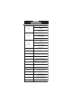
p H BUFFER TEMPERATURE DEPENDENCE The temperature has an effect on pH. The calibration buffer solutions are affected by temperature changes to a lesser degree than normal solutions. During calibration the instrument will automatically calibrate to the pH value corresponding to the measured or set temperature. TEMP pH BUFFERS ºC ºF 1. 68 3. 00 6. 86 7. 01 9. 18 10. 01 12. 45 0 32 1.67 3.08 6.98 7.13 9.46 10.32 13.38 5 41 1.67 3.06 6.95 7.10 9.39 10.24 13.18 10 50 1.67 3.04 6.
GOOD LABORATORY PRACTICE (GLP) GLP is a set of functions that allows the storage and retrieval of data regarding the maintenance and status of the electrode. All data regarding the last calibration is stored for the user to review when necessary. EXPIRED CALIBRATION This instrument allow the user to set the number of days before the next required calibration. This value can be set from 1 to 7 days. The default setting is OFF (disabled).
• The pH calibration slope in mV/pH normalized to 25 °C (the percentage is referred to the ideal value of 59.16 mV/pH). Note: If you calibrate using electrodes with pin the electrode condition and response gauges appear while the offset and slope are displayed. • The pH calibration buffers in calibrating order and with the selected resolutions used during calibration.
Notes: • Press GLP to return to measurement mode. • If calibration has not been performed, the instruments display “no CAL” message blinking. LOGGING Up to 100 logged samples can be stored into memory. LOGGING THE CURRENT DATA To store the current reading into memory press the LOG key while in measuring mode. The instrument will display the current date (mm.dd) on the primary LCD, the record number on the secondary LCD and the “LOG” tag will blink for a few seconds (see example below: record No.
The instrument will display the logged measurement value on the primary LCD and the record number on the secondary LCD, along with the “LOG” and “RCL” tags. Note: The “LOG” and “RCL” tags remain on LCD while in memory recall mode. Press the RCL key to return to measurement mode. Press the ARROW keys to scroll between same parameter for different records: Press the RANGE key to view additional data: • The mV value on the primary LCD and the temperature on the secondary LCD.
Note: On the screens where record number is not displayed press the SETUP key to display the record number. • To delete records press CLR key. The “dEL” message will be displayed on the primary LCD and the selected record on the secondary LCD. The “CFM” and the ”DEL” tags will blink: Press the ARROW keys to change the selected record. To delete all records press the SETUP key, ”ALL“ tag will appear on the secondary LCD. Press the CFM key to confirm the deleting of the selected record, or all records.
SETUP Setup mode allows viewing and modification of the following parameters: • Calibration Expiration Alarm • Current Time (hour & minute) • Current Date (year, month & day) • Beep Status • Instrument ID • Temperature Unit To enter the Setup mode press the SETUP key while the instrument is in measuring mode. Press SETUP key to exit SETUP mode. Select a parameter with the ARROW keys. Press the CAL key to change a parameter value. The selected parameter will start blinking.
Press the ARROW keys to change the displayed value. Press the CFM key to save the modified value or press the CAL key to escape without saving. CURRENT DATE Press the CAL key when the current date is displayed. The year will start blinking. Press the ARROW keys to change the year. Press the RANGE key. The month will start blinking. Press the ARROW keys to change the month. Press the RANGE key. The day will start blinking. Press the ARROW keys to change the day.
I NSTRUMENT ID Press the CAL key when “InId” is displayed. The instrument ID (“0000” to “9999”) will begin blinking. Press the ARROW keys to change the instrument ID value. Press the CFM key to save the modified instrument ID value or press the CAL key to cancel without saving the instrument ID. Note: The instrument ID is downloaded to a PC as part of a logged data set to identify it’s origin. TEMPERATURE UNIT Press CAL when “tenP” is displayed. The temperature unit will start blinking.
TEMPERATURE CALIBRATION ( for technical personnel only)) All the instruments are factory calibrated for temperature. Hanna’s temperature probes are interchangeable and no temperature calibration is needed when they are replaced. If the temperature measurements are inaccurate, temperature recalibration should be performed. For an accurate recalibration, contact your dealer or the nearest Hanna Customer Service Center, or follow the instructions below.
• When the reading is stable and close to the selected calibration point, “READY” tag will appear and “CFM” tag will blink. • Press CFM to confirm. The instrument returns to measurement mode. Note: If the reading is not close to the selected calibration point, “WRONG” tag will blink. Change the temperature probe and restart calibration. m V CALIBRATION (for technical personnel only) All the instruments are factory calibrated for mV.
PC INTERFACE Data transmission from the instrument to the PC can be done with the HI 92000 Windows® compatible software (optional). HI 92000 also offers graphing and on-line help feature. Data can be exported to the most popular spreadsheet programs for further analysis. To connect your instrument to a PC, use a standard USB cable connector. Make sure that your instrument is switched off and plug one connector to the instrument USB socket and the other to the USB port of your PC.
The instrument will answer for these commands with: where: is 02 ASCII code character (start of text) is 03 ASCII code character (end of text) : is 06 ASCII code character (recognized command) is 21 ASCII code character (unrecognized command) is 24 ASCII code character (corrupted command) COMMANDS REQUIRING AN ANSWER The instrument will answer for these commands with: where the checksum is the bytes sum of the answer
MDR GLP PAR Requests the instrument model name and firmware code (16 ASCII chars). Requests the calibration data record. The answer string contains: • GLP status (1 char): represents a 4 bit hexadecimal encoding.
NSL Requests the number of logged samples (4 chars). LODxxx Requests the xxxth record logged data. LODALL Requests all Log on demand data. The answer string contains: • pH resolution (2 chars): 00 - pH 0.001 resolution, 01 - pH 0.
ELECTRODE CONDITIONING & MAINTENANCE PREPARATION PROCEDURE Remove the protective cap of the pH electrode. DO NOT BE ALARMED IF SALT DEPOSITS ARE PRESENT. This is normal with electrodes. They will disappear when rinsed with water. During transport, tiny bubbles of air may form inside the glass bulb affecting proper functioning of the electrode. These bubbles can be removed by “shaking down” the electrode as you would do with a glass thermometer.
For refillable electrodes: If the filling solution (electrolyte) is more than 2½ cm (1”) below the fill hole, add HI 7082 or HI 8082 3.5M KCl Electrolyte Solution for double junction or HI 7071 or HI 8071 3.5M KCl+AgCl Electrolyte Solution for single junction electrodes. For faster response, unscrew the fill hole screw during measurements. For AMPHEL ® electrodes: If the electrode does not respond to pH changes, the battery is run down and the electrode should be replaced.
CLEANING PROCEDURE • General Soak in Hanna HI 7061 or HI 8061 General Cleaning Solution for approximately ½ hour. • Protein Soak in Hanna HI 7073 or HI 8073 Protein Cleaning Solution for 15 minutes. • Inorganic Soak in Hanna HI 7074 Inorganic Cleaning Solution for 15 minutes. • Oil/grease Rinse with Hanna HI 7077 or HI 8077 Oil and Fat Cleaning Solution.
TROUBLESHOOTING GUIDE SYMPTOMS PROBLE M SOLUTION Slow response/excessive D irty pH electrode. drift. C l e a n t h e e l e c t r od e a n d t h e n s oa k t h e t i p i n HI 7061 or HI 8061 for 30 minutes. Readings fluctuate up Clogged/dirty junction. and down (noise). Low electrolyte level (refillable electrodes only). Clean the electrode. Refill with fresh solution (for refillable electrodes only). Check cable and connectors. The meter does not accept the buffer solution for calibration.
TEMPERATURE CORRELATION FOR p H SENSITIVE GLASS The resistance of glass electrodes partially depends on the temperature. The lower the temperature, the higher the resistance. It takes more time for the reading to stabilize if the resistance is higher. In addition, the response time will suffer to a greater degree at temperatures below 25 ºC. Since the resistance of the pH electrode is in the range of 50 – 200 Mohm, the current across the membrane is in the pico Ampere range.
ACCESSORIES pH BUFFER SOLUTIONS HI 5003P pH 3.00 Buffer Sachets, 20 mL, 25 pcs HI 70004P pH 4.01 Buffer Sachets, 20 mL, 25 pcs HI 70007P pH 7.01 Buffer Sachets, 20 mL, 25 pcs HI 70010P pH 10.01 Buffer Sachets, 20 mL, 25 pcs HI 5003 pH 3.00 Buffer Solution, 500 mL HI 7001L pH 1.68 Buffer Solution, 500 mL HI 7004L pH 4.01 Buffer Solution, 500 mL HI 7006L pH 6.86 Buffer Solution, 500 mL HI 7007L pH 7.01 Buffer Solution, 500 mL HI 7009L pH 9.18 Buffer Solution, 500 mL HI 7010L pH 10.
ORP PRETREATMENT SOLUTIONS HI 7091L Reducing Pretreatment Solution, 500 mL HI 7092L Oxidizing Pretreatment Solution, 500 mL pH ELECTRODES All electrodes with code ending with P are supplied with BNC & pin connector and 1 m (3.3') cable, as shown below. HI 1043P; Use: strong acid/alkali. Glass-body, double junction, refillable, combination pH electrode. HI 1053P; Use: emulsions. 9.5mm DIA 0.37" 12 mm 0.5" HI 1043 120 mm 4.
HI 1048P; Use: wine measurements. Glass-body, refillable pH electrode with open junction, (PTFE) collar. HI 1048 ORP ELECTRODES HI 3131P; Use: titration. Glass-body, refillable, combination platinum ORP electrode. 12 mm 0.5" HI 3131 150 mm 5.9" "S" VERSION Consult the Hanna General Catalog for more electrodes with BNC and pin connectors. EXTENSION CABLE FOR SCREW-TYPE ELECTRODES (SCREW TO BNC ADAPTER) HI 7855/1 Extension cable 1 m (3.3') long HI 7855/3 Extension cable 3 m (9.
HI 76404N Electrode holder HI 92000 Windows® compatible software. RECOMMENDATIONS FOR USERS Before using these products, make sure they are entirely suitable for the environment in which they are used. Operation of these instruments in residential areas could cause unacceptable interferences to radio and TV equipment, requiring the operator to follow all necessary steps to correct interferences. The glass bulb at the end of the pH electrode is sensitive to electrostatic discharges.
Hanna Instruments Inc. Highland Industrial Park 584 Park East Drive Woonsocket RI 028985 USA Local Sales and Customer Service office Hanna Instruments United States Inc. Highland Industrial Park 584 Park East Drive Woonsocket RI 028985 USA Tel. (800) 426 6287 Fax (401) 765 7575 www.hannainst.com/usa Technical Support for customers Telephone (800) 426 6287 Fax (401) 765 7575 E-mail tech@hannainst.