Instruction Manual HI 2550 Multiparameter pH/ORP/°C EC/TDS/NaCl Bench Meter w w w. h a n n a i n s t .
Dear Customer, Thank you for choosing a Hanna Instruments product. Please read this instruction manual carefully before using this instrument. This manual will provide you with the necessary information for correct use of this instrument, as well as a precise idea of its versatility. If you need additional technical information, do not hesitate to e-mail us at tech@hannainst.com.
PRELIMINARY EXAMINATION Remove the instrument from the packing material and examine it carefully to make sure that no damage has occurred during shipping. If there is any damage, notify your Dealer or the nearest Hanna Customer Service Center. Each instrument is supplied with: • HI 1131B Glass-body Combination pH Electrode with 1 m (3.3') Cable • HI 76310 Conductivity / TDS probe • HI 7662 Temperature Probe • HI 76404N Electrode Holder • pH 4.01 & 7.
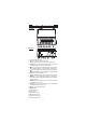
FUNCTIONAL DESCRIPTION Front Panel Rear Panel 1) Liquid Crystal Display (LCD). 2) CAL key, to enter and exit calibration mode. RCL key (alternate function), to enter and exit memory recall. 3) CFM/GLP key, to confirm calibration selection, different setup values or to display Good Laboratory Practice information. 4) ºC key, to manually increase temperature value or other parameters. TC key (alternate function), to view temperature coefficient value.
SPECIFICATIONS –2.0 to 16.0 p H –2.00 to 16.00 p H –2.000 to 16.000 p H ±999.9 mV (ISE & ORP) ±2000 mV (ISE & ORP) RANGE 0.00 to 29.99 μ S/cm 30.0 to 299.9 μ S/cm 300 to 2999 μ S/cm 3.00 to 29.99 mS/cm 30.0 to 200.0 mS/cm u p to 500.0 mS/cm u ncomp ensa ted (*) cond u ctivity 0.00 to 14.99 p p m 15.0 to 149.9 p p m 150 to 1499 p p m 1.50 to 14.99 g /l 15.0 to 100.0 g /l up to 400.0 g/l u ncomp ensa ted (*) TD S (with 0.80 fa ctor) 0.0 to 400.0% Na Cl –20.0 to 120.0 ºC (p H, E C ra ng e) 0.1 p H 0.
Rel mV offset range pH Calibration ±2000 mV 1, 2, 3, 4 or 5 point calibration, 7 standard buffers available (1.68, 4.01, 6.86, 7.01, 9.18, 10.01, 12.45), and 2 custom buffers E C Calibration 1 point slope calibration; 6 buffers available: 84.0, 1413 μS/cm 5.00, 12.88, 80.0, 111.8 mS/cm 1 point offset: 0.00 μS/cm NaCl Calibration 1 point with HI 7037L buffer (optional) Temperature compensation Manual or Automatic from: –20.0 to 120.0 ºC (pH RANGE ) –20.0 to 120.
OPERATIONAL GUIDE POWER CONNECTION Plug the 12 VDC adapter into the power supply socket. Notes: • This instrument uses non volatile memory to retain the calibration parameters and all other settings, even when unplugged. • Make sure a fuse protects the main line. ELECTRODE AND PROBE CONNECTIONS For pH or ORP measurements connect an electrode with internal reference to the BNC connector on the back of the instrument.
• The pH is displayed on the primary LCD and the temperature on the secondary LCD. pH • If the reading is out of range, the closest full-scale value will be displayed blinking on the primary LCD. pH If measurements are taken successively in different samples, it is recommended to rinse the electrode thoroughly with deionized water or tap water and then with some of the next sample to prevent cross-contamination. The pH reading is affected by temperature.
• The instrument displays the mV reading on the primary LCD and the temperature on the secondary LCD line. mV • If the reading is out of range, the closest full-scale value will be displayed blinking on the primary LCD. mV RELATIVE mV MEASUREMENTS • Press the ALT&MODE keys simultaneously while in mV range. The “rEL” and “mV” tags are displayed for about one second. After one second the temperature will be displayed on the secondary LCD and the “mV” tag will blink.
• If LOCK key was pressed and the reading goes out of range, the full-scale value of the frozen range will be displayed blinking. The conductivity reading is affected by temperature. Three options for temperature compensation are available in conductivity measurement mode. Automatic (ATC): The conductivity probe has a built-in temperature sensor; the temperature value is used to automatically compensate the EC/TDS reading.
TDS MEASUREMENTS Press the ALT&MODE keys while in EC range. The instrument will switch to TDS measuring range. The TDS reading will be displayed on the primary LCD and the temperature reading on the secondary LCD. • If the reading is out of range, the full-scale value (100.0 for MTC/ATC mode or 400.0 for uncompensated TDS) will be displayed blinking. • If LOCK was pressed and the reading goes out of range, the full-scale value of the frozen range will be displayed blinking.
AUTO-RANGING The EC and TDS scales are auto-ranging. The meter automatically sets the scale with the highest possible resolution. By pressing ALT&LOCK, the auto-ranging feature is disabled and the current range is frozen on the LCD. The “Auto” “Off” (auto-ranging disabled) tags will be displayed on the LCD for a few seconds. To restore the auto-ranging option, press ALT&LOCK again. The “Auto” “On” (auto-ranging enabled) tags will be displayed on the LCD for a few seconds.
p H CALIBRATION Calibrate the instrument frequently, especially if high accuracy is required. The instrument should be recalibrated: • Whenever the pH electrode is replaced. • At least once a day. • After testing aggressive chemicals. • If “CAL” “INTV” tags are blinking during measurement. Every time you calibrate the instrument use fresh buffers and perform an electrode Cleaning Procedure (see page 53). PREPARATION Pour small quantities of the buffer solutions into clean beakers.
FIVE FIVE-- POINT CALIBRATION • Submerse the pH electrode and the temperature probe approximately 3 cm (1¼”) into a buffer solution and stir gently. The temperature probe should be close to the pH electrode. • Press CAL. The “CAL” and “ ” tags will appear and the “7.01” buffer will be displayed on the secondary LCD. 3 cm (1¼") BUF • If necessary, press the ARROW keys to select a different buffer value. • The “ ” tag will blink on the LCD until the reading is stable.
• If necessary, press the ARROW keys to select a different buffer value. • The “ ” tag will blink on the LCD until the reading is stable. • When the reading is stable and close to the selected buffer, the “READY” tag will be displayed and the “CFM” tag will blink. • Press CFM to confirm calibration. • The calibrated value is then displayed on the primary LCD and the fourth expected buffer value on the secondary LCD.
ONE-POINT CALIBRATION Two SETUP selectable options are available: “Pnt” and “OFFS”. If the “Pnt” option is selected, the new calibration point overrides an existing one. The adjacent slopes will be reevaluated. If the “OFFS” option is selected, an electrode offset correction is performed. The adjacent slopes will remain unchanged. • Proceed as described in “FOUR, THREE or TWO-POINT CALIBRATION” section. • Press CAL after the first calibration point was confirmed.
• Each time a buffer is confirmed, the new calibration data replaces the old calibration data for the corresponding buffer. If current buffer has no previous data stored and the calibration is not full (five buffers), the current buffer is added to the existing calibration. If the existing calibration is full, the instrument asks which buffer to replace. Press the ARROW keys to select another buffer to be replaced. Press CFM to confirm the buffer that will be replaced.
p H BUFFER TEMPERATURE DEPENDENCE The temperature has an effect on pH. The calibration buffer solutions are affected by temperature changes to a lesser degree than normal solutions. During calibration the instrument will automatically calibrate to the pH value corresponding to the measured or set temperature. TEMP pH BUFFERS ºC ºF 1.68 4.01 6.86 7.01 9.18 10.01 12.45 0 32 1.67 4.01 6.98 7.13 9.46 10.32 13.38 5 41 1.67 4.00 6.95 7.10 9.39 10.24 13.18 10 50 1.67 4.00 6.92 7.
RELATIVE m V CALIBRATION • Press CAL when the instrument is in RELATIVE mV measurement mode. The “mV” and “ ” tags will be displayed. Absolute mV is displayed on the primary LCD and “AbS” message is displayed on the secondary LCD. • When the absolute reading is stable and in measurement range, the instrument asks for confirmation. • If the reading is out of range, “WRONG” tag will be displayed. • Press CFM to confirm the absolute value. The instrument will display 0.
CAL BUF S Select the desired value with the ARROW keys, if necessary. When the reading is stable, “READY” tag is displayed and “CFM” tag starts blinking on the LCD, asking for confirmation. CAL CFM READY BUF S Press CFM to confirm calibration. The instrument stores the calibration value and returns to measurement mode. Notes: • If the reading is too far from the expected value, the “WRONG” and “ ” tags will blink. Calibration can not be confirmed.
CONDUCTIVITY VERSUS TEMPERATURE CHART The conductivity of an aqueous solution is a measure of its ability to carry an electrical current by means of ionic motion. The conductivity invariably increases with increasing temperature. It is affected by the type and number of ions in the solutions and by the viscosity of the solution itself. Both parameters are temperature dependent.
NaCl CALIBRATION NaCl calibration is a one-point calibration at 100.0% NaCl. Use the HI 7037L calibration solution (sea water solution) as a 100% NaCl calibration solution. Rinse the probe with some of the calibration solution or deionized water. Submerse the probe into HI 7037L solution. The sleeve holes must be completely submersed. Tap the probe repeatedly to remove any air bubbles that may be trapped inside the sleeve. To enter NaCl calibration select the NaCl range and press CAL.
GOOD LABORATORY PRACTICE (GLP) GLP is a set of functions that allows storage and retrieval of data regarding the maintenance and status of the electrode. All data regarding pH, Rel mV, EC and NaCl calibration is stored for the user to review when necessary. EXPIRED CALIBRATION For pH calibration, this instrument allows the user to set the number of days before the next required pH calibration. This value can be set from 1 to 7 days. The default setting is OFF (disabled).
• The pH calibration slope (the GLP slope is the average of the calibration slopes; the percentage is referred to the ideal value of 59.16 mV/pH). • The calibration buffers in order. The first pH calibration buffer: The second pH calibration buffer: The third pH calibration buffer: CAL pH BUF The fourth pH calibration buffer: CAL pH BUF The fifth pH calibration buffer: CAL pH BUF Notes: • The “OLd” message displayed beside the pH value means that this buffer was not used during last calibration.
- or the number of days until the calibration alarm will be displayed. - or if expired (7 days ago). INTV CAL • The instrument ID. R elative mV CALIBRATION DATA Relative mV calibration data is stored automatically after a successful calibration. To view the Relative mV calibration data, press GLP when the instrument is in Relative mV measurement mode. The instrument will display the time (hh:mm) of the last calibration.
EC CALIBRATION DATA EC calibration data is stored automatically after a successful calibration. To view the EC calibration data, press GLP when the instrument is in EC measurement mode. The instrument will display the time (hh:mm) of the last calibration. Use the ARROW key to scroll through the calibration data: • The date (yyyy:mm:dd). • The EC calibration buffer. • The cell constant. • The calibration offset factor. • The reference temperature. • The temperature coefficient.
• The temperature compensation mode. • The instrument ID. N aCl CALIBRATION DATA NaCl calibration data is stored automatically after a successful calibration. To view the NaCl calibration data, press GLP when the instrument is in NaCl measurement mode. The instrument will display the time (hh:mm) of the last calibration. Use the ARROW key to scroll through the calibration data: • The date (yyyy:mm:dd). • The salinity coefficient. • The cell constant. • The reference temperature.
• The temperature compensation mode. • The instrument ID. Notes: • If no temperature compensation is selected during calibration, the temperature coefficient is not displayed in GLP. • Press GLP at any moment and the instrument will return to measurement mode. • If calibration has not been performed on the selected range, the instrument displays “no CAL” message blinking. CAL LOGGING FUNCTION Up to 700 logged samples can be stored into memory.
followed by the number of free records: If there are less than 6 memory locations remaining, the record number and “Lo” message will be displayed to alert the user. If the log space is full (200 records), “FULL LOG” message will be displayed and no more data will be saved. When LOG is pressed, a complete set of information is stored: date, time, pH, mV, EC, TDS, NaCl temperature and calibration data. LOT LOGGING Select “StAb” (stability logging) or the desired time interval.
VIEW LOGGED DATA Press the ALT&RCL keys while in measurement mode to retrieve the stored information.
Press CFM to view record information. • If RCL was entered while in pH measurement range: LOG pH In Rel mV range: In EC measurement range: In TDS measurement range: In NaCl measurement range: Use the ARROW keys to scroll through the records.
Note: The instrument will automatically skip log records from other measurement ranges. To view additional information press RANGE: For pH • The mV value on the primary LCD and the temperature value on the secondary LCD. • The time on the primary LCD, along with “TIME” tag and the record number on the secondary LCD. TIME LOG • The date on the primary LCD, along with “DATE” tag. • The calibration offset on the primary LCD and “OFS” message on the secondary LCD.
The “dEL” message is displayed on the primary LCD and the selected record on the secondary LCD, along with ”LOG” tag. • The ARROW keys can be used to change the record or lot number. • Press SETUP to delete all records/lots. The display will show “dEL” in the primary LCD and “ALL” in the secondary LCD. • Press CFM to confirm delete. While deleting the “ ” tag will blink. • Press CAL or RANGE or CLR to escape and return to the RCL screen.
• The cell constant on the primary LCD and “CEL” message on the secondary LCD line. • The reference temperature on the primary LCD and “rEF” message on the secondary LCD. • The temperature coefficient on the primary LCD and “tc” message on the secondary LCD. • The temperature compensation mode. For TDS Range • The temperature reading as described in pH range. • The conductivity value on the primary LCD and the temperature value on the secondary LCD. • The time and the date as described in pH Range.
For NaCl Range • The conductivity and temperature reading value as described in TDS Range. • The time and date as described in pH Range. • The salinity factor on the primary LCD and “cF” message on the secondary LCD, with “LOG” and “NaCl” tags displayed. • The reference temperature, the temperature compensation mode and the cell constant message as described above.
SETUP Setup mode allows viewing and modifying the following instrument parameters. In according with the selected range, SETUP menu allows the possibility to view and /or change specific range parameters and common parameters (for all the ranges).
EXPIRED CALIBRATION ALARM Press CAL when the calibration time-out is displayed. Calibration time-out (“OFF” or “1” to “7” days) will start blinking. Press the ARROW keys to change the calibration time-out value. Press CFM to save the modified calibration time-out value. Press CAL to escape without saving. LOG INTERVAL Press CAL when log interval is displayed. The log interval is selected blinking (“MAn” for log on demand, “StAb” log on stability, interval in seconds or minutes).
Note: To remove a custom buffer from the calibration list enter custom buffer press CAL key then press CLR key. The “no” “cb1” or “cb2” message will be displayed and the instrument return for the SETUP parameter scroll mode. ONE-POINT CALIBRATION BEHAVIOR Press CAL when “1 Pnt” message is displayed on the secondary LCD. One of the two options (“Pnt” or “OFFS”) will start blinking (see pH CALIBRATION PROCEDURE for details, page 13). Press the ARROW keys to toggle between “Pnt” and “OFFS” options.
CURRENT DATE Press CAL when the current date is displayed. The year will start blinking. Press the ARROW keys to change the year. Press RANGE. The month will start blinking. Press the ARROW keys to change the month. Press RANGE. The day will start blinking. Press the ARROW keys to change the day. Press CFM to save the modified value. Press CAL to escape without saving. BEEP STATUS Press CAL when the beep status is displayed. Beep status (“On” or “OFF”) will start blinking.
I NSTRUMENT ID Press CAL when “InId” is displayed. The instrument ID (“0000“ to “9999“) will start blinking. Press the ARROW keys to change the instrument ID value. Press CFM to save the modified instrument ID value. Press CAL to escape without saving. Note: The instrument ID is downloaded to a PC as part of a logged data, set to identify its origin. TEMPERATURE UNIT Press CAL when “tnP“ is displayed. The temperature unit will start blinking. Press the ARROW keys to change the option.
TDS FACTOR Press CAL when “tdS” is displayed. The TDS factor will start blinking. Press the ARROW keys to change the TDS factor (0.40 to 0.80). Press CFM to save the modified TDS factor. Press CAL to escape without saving. TEMPERATURE COMPENSATION COEFFICIENT Press CAL when the temperature compensation coefficient is displayed. The temperature compensation coefficient will start blinking. Press the ARROW keys to change the temperature compensation coefficient. (0.00 to 6.00 %/ºC).
TEMPERATURE CALIBRATION ( f o r t e c h n i c a l p e r s o n n e l o n l yy)) The instrument has two temperature channels: one that measures the temperature from the HI 7662 probe while the instrument is in pH/mV range and the other that measures temperature from the EC probe while the instrument is in EC/TDS/NaCl range. All the instruments are factory calibrated for temperature on both channels. Hanna’s temperature probes are interchangeable and no temperature calibration is needed when they are replaced.
• Submerse the temperature probe (or EC probe) in the second vessel as near as possible to the calibrated thermometer. Allow a few seconds for the probe to stabilize. • Use the ARROW keys to set the reading on the secondary LCD to that of the hot water. • When the reading is stable and close to the selected calibration point, “READY” tag will appear and “CFM” tag will blink. • Press CFM to confirm. The instrument memorize calibration and restart in measurement mode.
m V CALIBRATION ( f o r t e c h n i c a l p e r s o n n e l o n l yy)) All the instruments are factory calibrated for mV. Hanna’s ORP electrodes are interchangeable and no mV calibration is needed when they are replaced. If the mV measurements are inaccurate, mV recalibration should be performed. For an accurate recalibration, contact your dealer or the nearest Hanna Customer Service Center or follow the instructions below. A two-point calibration can be performed at 0.0 mV and 1800.0 mV.
PC INTERFACE Data transmission from the instrument to the PC can be done with the HI 92000 Windows® compatible software (optional). HI 92000 also offers graphing and on-line help feature. Data can be exported to the most popular spreadsheet programs for further analysis. To connect your instrument to a PC, use a standard USB cable connector. Make sure that your instrument is switched off and plug one connector to the instrument USB socket and the other to the USB port of your PC.
Change the instrument range according with the parameter value (xx): • xx=00 pH range/0.001 resolution • xx=01 pH range/0.01 resolution • xx=02 pH range/0.1 resolution • xx=03 mV range • xx=04 Relative mV range • xx=06 EC range • xx=07 TDS range • xx=08 NaCl range The instrument sends the “ACK” (6) character every time a command is recognized and a “NAK” (21) character for invalid commands.
MDR GLP • Reading status (2 chars): R - in range, O - over range, U - under range. First character corresponds to the appropriate range reading. Second character corresponds to mV reading (if exist). • Primary reading (corresponding to the selected range) - 7 ASCII chars, including sign and decimal point. • Secondary reading (only when primary reading is not mV, EC, NaCl, TDS) - 7 ASCII chars, including sign and decimal point.
• EC calibration data (if available), which contains: • the number of calibrated standards (1 char) • the offset factor, with sign and decimal point (7 chars) • the cell constant, with sign and decimal point (7 chars) • the calibration time, yymmddhhmmss (12 chars) • standards information (for each standard) • standard value, with sign and decimal point (7 chars).
• Calibration alarm time out for pH range (2 chars) • SETUP information (2 chars): 8 bit hexadecimal encoding.
GLDxxxff: Requests the records of the “xxx” lot number. The records are sent in frames of 10 records; “ff” is the frame number (01 first frame). (Example: Lot 13 has 53 records. The records will be sent in 6 frame, 5 with10 records and 1 with 3 records.) Command Parameters: xxx - Lot number (eq: for lot number 1 xxx = 001) ff - requested frame number - first frame is labeled 01 “Err3” log on demand empty. “Err4” requested set parameter is not available. “Err5” command argument is wrong.
ELECTRODE CONDITIONING & MAINTENANCE PREPARATION PROCEDURE Remove the protective cap of the pH electrode. DO NOT BE ALARMED IF SALT DEPOSITS ARE PRESENT. This is normal with electrodes. They will disappear when rinsed with water. During transport, tiny bubbles of air may form inside the glass bulb affecting proper functioning of the electrode. These bubbles can be removed by “shaking down” the electrode as you would do with a glass thermometer.
For refillable electrodes: If the filling solution (electrolyte) is more than 2½ cm (1”) below the fill hole, add HI 7082 or HI 8082 3.5M KCl Electrolyte Solution for double junction or HI 7071 or HI 8071 3.5M KCl+AgCl Electrolyte Solution for single junction electrodes. For faster response, unscrew the fill hole screw during measurements. For AMPHEL ® electrodes: If the electrode does not respond to pH changes, the battery is run down and the electrode should be replaced.
pH ELECTRODE CLEANING PROCEDURE • General Soak in Hanna HI 7061 or HI 8061 General Cleaning Solution for approximately ½ hour. • Protein Soak in Hanna HI 7073 or HI 8073 Protein Cleaning Solution for 15 minutes. • Inorganic Soak in Hanna HI 7074 Inorganic Cleaning Solution for 15 minutes. • Oil/grease Rinse with Hanna HI 7077 or HI 8077 Oil and Fat Cleaning Solution.
TROUBLESHOOTING GUIDE SYMP TOMS P ROBL E M Slow response/excessive drift D irty pH electrode. measuring pH. SOL UTION S oa k th e el ectrod e ti p i n HI 7061 or HI 8061 for 30 minutes and then clean the electrode. Readings fluctuate up and Clogged/dirty junction. Clean the electrode. down (noise). L o w e l e c t r o l y t e l e v e l Refill with fresh solution (for ( r e f i l l a b l e p H e l e c t r o d e s refillable pH electrodes only). I n s e r t t h e s l e e v e . Ta p t h e only).
TEMPERATURE CORRELATION FOR p H SENSITIVE GLASS The resistance of glass electrodes partially depends on the temperature. The lower the temperature, the higher the resistance. It takes more time for the reading to stabilize if the resistance is higher. In addition, the response time will suffer to a greater degree at temperatures below 25 ºC. Since the resistance of the pH electrode is in the range of 50 – 200 Mohm, the current across the membrane is in the pico Ampere range.
ACCESSORIES pH BUFFER SOLUTIONS HI 70004P pH 4.01 Buffer Sachets, 20 mL, 25 pcs HI 70007P pH 7.01 Buffer Sachets, 20 mL, 25 pcs HI 70010P pH 10.01 Buffer Sachets, 20 mL, 25 pcs HI 7001L pH 1.68 Buffer Solution, 500 mL HI 7004L pH 4.01 Buffer Solution, 500 mL HI 7006L pH 6.86 Buffer Solution, 500 mL HI 7007L pH 7.01 Buffer Solution, 500 mL HI 7009L pH 9.18 Buffer Solution, 500 mL HI 7010L pH 10.01 Buffer Solution, 500 mL HI 8004L pH 4.01 Buffer Solution in FDA approved bottle, 500 mL HI 8006L pH 6.
ORP PRETREATMENT SOLUTIONS HI 7091L Reducing Pretreatment Solution, 500 mL HI 7092L Oxidizing Pretreatment Solution, 500 mL CONDUCTIVITY SOLUTIONS HI 70030P 12880 μS/cm (μmho/cm), 20 mL sachets (25 pcs.) HI 70031P 1413 μS/cm (μmho/cm), 20 mL sachets (25 pcs.) HI 70033P 84 μS/cm (μmho/cm), 20 mL sachets (25 pcs.) HI 70039P 5000 μS/cm (μmho/cm), 20 mL sachets (25 pcs.
HI 70442M* 1500 ppm (mg/L), 250 mL HI 70442L* 1500 ppm (mg/L), 500 mL * 1500 ppm TDS have an approximate conversion factor of: 0.65 ppm = 1 μS/cm conversion rate. pH ELECTRODES All electrodes part numbers ending in B are supplied with a BNC connector and 1 m (3.3') cable, as shown below : HI 1043B Glass-body, double junction, refillable, combination pH electrode. Use: strong acid/alkali. HI 1053B Glass-body, triple ceramic, conic shape, refillable, combination pH electrode. Use: emulsions.
HI 1330B Glass-body, semimicro, single junction, refillable, combination pH electrode. Use: laboratory, vials. HI 1331B Glass-body, semimicro, single junction, refillable, combination pH electrode. Use: flasks. HI 1230B Plastic-body (PES), double junction, gel-filled, combination pH electrode. Use: general, field. HI 2031B Glass-body, semimicro, conic, refillable, combination pH electrode. Use: semisolid products. HI 1332B Plastic-body (PES), double junction, refillable, combination pH electrode.
FC 100B Plastic-body (PVDF), double junction, refillable, combination pH electrode. Use: general purpose for food industry. FC 200B Plastic-body (PVDF), open junction, conic, Viscolene, non-refillable, combination pH electrode. Use: meat & cheese. FC 210B Glass-body, double junction, conic, Viscolene, non-refillable, combination pH electrode. Use: milk, yogurt. FC 220B Glass-body, triple-ceramic, single junction, refillable, combination pH electrode. Use: food processing.
HI 1413B Glass-body, single junction, flat tip, Viscolene, non-refillable, combination pH electrode. Use: surface measurement. ORP ELECTRODES HI 3131B Glass-body, refillable, combination platinum ORP electrode. Use: titration. HI 3230B Plastic-body (PES), gel-filled, combination platinum ORP electrode. Use: general purpose. HI 4430B Plastic-body (PES), gel-filled, combination gold ORP electrode. Use: general purpose.
EXTENSION CABLE FOR SCREW-TYPE ELECTRODES (SCREW TO BNC ADAPTER) HI 7855/1 HI 7855/3 Extension cable 1 m (3.3') long Extension cable 3 m (9.9') long HI 7855 SERIES CABLE CONNECTORS CONNECTOR AND 3.0 mm (0.
RECOMMENDATIONS FOR USERS Before using this product, make sure that it is entirely suitable for the environment in which it is used. Operation of this instrument in residential areas could cause unacceptable interferences to radio and TV equipment, requiring the operator to follow all necessary steps to correct interferences. The glass bulb at the end of the pH electrode is sensitive to electrostatic discharges. Avoid touching this glass bulb at all times.
Hanna Instruments Inc. Highland Industrial Park 584 Park East Drive Woonsocket RI 028985 USA Local Sales and Customer Service office Hanna Instruments United States Inc. Highland Industrial Park 584 Park East Drive Woonsocket RI 028985 USA Tel. (800) 426 6287 Fax (401) 765 7575 www.hannainst.com/usa Technical Support for customers Telephone (800) 426 6287 Fax (401) 765 7575 E-mail tech@hannainst.