Instruction Manual HI 4221 & HI 4222 pH/mV/ISE/Temperature Bench Meters w w w. h a n n a i n s t .
Dear Customer, Thank you for choosing a Hanna Instruments product. This manual will provide you with the necessary information for correct use of the instrument. Please read this instruction manual carefully before using the instrument. If you need additional technical information, do not hesitate to e-mail us at tech@hannainst.com or see the back side of this manual for our worldwide sales and technical service contacts. These instruments are in compliance with directives.
TABLE OF CONTENTS WARRANTY ...................................................................................................................................... 2 PRELIMINARY EXAMINATION .............................................................................................................. 4 GENERAL DESCRIPTION ...................................................................................................................... 4 FUNCTIONAL DESCRIPTION ...............................................
PRELIMINARY EXAMINATION Remove the instrument from the packing material and examine it carefully to make sure that no damage has occurred during shipping. If there is any damage, notify your dealer or the nearest Hanna Service Center. The meters are supplied complete with: • HI 1131B Glass-body Combination pH Electrode • HI 7662-T Temperature probe • pH 4.01 & 7.
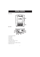
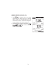
FUNCTIONAL DESCRIPTION HI 4221 DESCRIPTION FRONT PANEL REAR PANEL 1) 2) 3) 4) 5) 6) 7) 8) 9) Liquid Crystal Display (LCD) Main Keyboard USB connector ON/OFF switch Power adapter socket RS232 serial communication connector Temperature probe socket BNC electrode connector for pH/ORP measurements Reference input socket 5
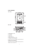
HI 4222 DESCRIPTION FRONT PANEL REAR PANEL 1) Liquid Crystal Display (LCD) 2) Main Keyboard 3) USB connector 4) ON/OFF switch 5) Power adapter socket 6) RS232 serial communication connector 7) Temperature probe socket (Channel 2) 8) BNC electrode connector for pH/ORP/ISE measurements (Channel 2) 9) Reference input socket (Channel 2) 10) Temperature probe socket (Channel 1) 11) BNC electrode connector for pH/ORP/ISE measurements (Channel 1) 12) Reference input socket (Channel 1) 6
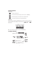
KEYBOARD DESCRIPTION FUNCTION KEYS To enter/exit calibration mode. To select the desired measurement mode, pH, mV, Rel mV (or ISE – HI 4222 only). To enter Setup (System, pH, mV or ISE) and to access Log Recall function. To obtain general informations about the selected option/operation. VIRTUAL KEYS The upper row keys are assigned to the virtual keys placed on the bottom of the LCD, which allow you to , and in perform the displayed function, depending on the current menu (e.g. Measure mode).
SPECIFICATIONS HI 4221 HI 4222 –2.000 to 20.000 pH RANGE ±2000.0 mV 1* 10–6 to 9.99* 1010 conc. – –20.0 to 120.0 ºC / –4.0 to 248.0 ºF / 253.15 to 393.15 K 0.1 pH / 0.01 pH / 0.001 pH RE SOLUTION 0.1 mV 1 conc. / 0.1 conc. / 0.01 conc. / 0.001 conc. – 0.1 ºC / 0.1 ºF / 0.1 K ±0.1 pH ±0.01 pH ±0.002 pH ± 1LSD ACCURACY @20 ºC / 68 ºF ±0.2 mV ± 1LSD ±0.5% (monovalent ions) ±1% (divalent ions) – ±0.2 ºC / ±0.4 ºF / ±0.2 K Relative mV offset range ±2000.
OPERATIONAL GUIDE POWER CONNECTION Plug the 12 Vdc adapter into the power supply socket. Notes: • These instruments use non volatile memory to retain the pH, Ion calibrations and all other settings, even when unplugged. • Make sure a fuse protects the main line. ELECTRODE AND PROBE CONNECTIONS For pH or ORP measurements connect a pH/ORP electrode with internal reference to the BNC connector located on the rear panel of the instrument (for the desired channel – HI 4222 only).
CHANNEL SELECTION (HI 4222 only) • Press while in Measure mode to access channel selection menu. Four available options will be displayed: Channel 1, Channel 2, or multi-channel with the first or the second channel focused. The “Choose Channel Configuration” message is displayed in the Reminder messages area. , • Select the desired option by pressing the appropriate key: , or . The instrument will enter in the selected option Measure mode.
DISPLAYING MODES For each measurement mode (pH, mV, Rel mV or Ion) the following display configurations are available: Basic, Good Laboratory Practice (GLP), Graph and Log History. Basic Accessing this option, the measured value and its units are displayed on the LCD, along with the temperature value, temperature compensation mode, and GLP data. To choose the Basic displaying mode: • Press while in Measure mode. The “Choose Display Configuration” message will be displayed in the Reminder messages area.
Graph Accessing this option, the online graph with currently logged values (pH, mV, Rel mV, or ISE vs. Seconds) will be displayed. If there is no active log, the previously logged data for the selected parameter will be plotted. Notes: • If no data were logged, the graph displaying mode will not be accessible. • If no automatic log is saved, the offline graph will not be available. To access the offline / online graph: • Press while in Measure / Logging mode.
When the online graph is displayed: • Use and to move the graph along X (Time) axis. • Press to access the zoom menu for Y axis. Use or for zooming Y (parameter) axis. to return to the main menu. • Press When the offline graph is displayed: • Use the arrow keys to move the graph along X (Time) and Y (parameter) axes. • Press to access the zoom menu for X and Y axes. Use , or / / / to switch between the active zooming axes. Press or to zoom the selected axis.
SYSTEM SETUP The System Setup menu allows the user to customize the user interface, consult the meter information, set the external serial communication interface and to restore the manufacturer settings. Accessing System Setup • Press while in Measure mode. . The system setup options will be displayed on • Press the LCD. To access a System Setup option: or to highlight the desired option. • Use • Press to access the selected option. The following is a detailed description of the System Setup option screen.
• Use or to select the Beeper option. • Press and use or to highlight the desired beeper status option you want to modify. • Press and use or to highlight the desired option. • Press to confirm your selection and return to the Beeper to return to the Beeper menu without menu or press changing.
To set the GLP Data: while in Measure mode. • Press • Press . • Use or to select the GLP Data option. • Press and use or to highlight the desired option. • Press to edit the desired information. The Text Editor menu will be displayed on the LCD. • Enter the desired information by accepting the highlighted character which is added to the text bar, using . The and keys help the user select the desired character.
• Use or to select the Date & Time option. • Press and use or to highlight the desired option you want to modify. • Press to confirm your selection. Use / to select next/previous entry to be edit. Press and use or to set the desired value, then press to save the modified value (for Set Date and Time option). For the other two options press to confirm your selection or . and select one of the displayed options with • Press to confirm your selection and return to the Date & Time options.
Language This option allows the user to choose the desired language in which all information will be displayed. To select the Language: • Press while in Measure mode. • Press . • Use or to select the Language option. • Press and use or to highlight the desired language. • Press to confirm your selection and return to the System to return to the System Setup Setup menu or press menu without changing.
Note: All the instruments are factory calibrated for mV and temperature. After one year following factory calibration, the “Factory Calibration Due” message will appear on the LCD, in the Reminder messages area, notifying the user that the instrument should be taken to the nearest Hanna Customer Service for factory calibration. To view the Meter Information: • Press while in Measure mode. • Press . • Use or to select the Meter Information option.
pH SETUP The pH Setup menu allows the user to set the parameters associated with pH measurement and calibration. These parameters can be set specifically for each channel (HI 4222 only). The settings will be applied only to the active channel. Accessing pH Setup • Press while in Measure mode and then to select pH range for the desired channel. • Press and then to access pH Setup menu. To access a pH Setup option: • Use or to highlight the desired option. • Press to access the selected option.
To set one of the Temperature options: • Press while in pH Measure mode. • Press . • Use or to select the Temperature option. • Press and use or to highlight the desired Temperature option you wish to modify. • Press and use or to highlight the desired option (for Temperature Source & Unit options) or use or to adjust the temperature value between the displayed limits (for Manual Temperature option).
1st Cal. Point Two options are available for the 1st Cal. Point parameter: Point and Offset. If Point option is selected, the slope values adjacent to the calibration points will be reevaluated (normal calibration). If at least a two-point calibration has been performed and an offset correction of the electrode is wanted (maintaining the existing slope values), perform a one-point calibration using the Offset option. To set the 1st Cal. Point: • Press while in pH Measure mode. • Press .
to exit custom buffer edit menu. If the Saving Confirmation is enabled, press to accept • Press the modified option, to escape without saving or to return to the editing mode. Otherwise, the modified option is saved automatically. key to select the next custom buffer to be set or press to return to Calibration options. • Use Edit Buffer Group Accessing this option the user can edit the desired group of five pH buffers for automatic buffer recognition (Automatic Buffer Entry Type).
Set Reminder Period If choosing Daily or Periodic options for the Calibration Reminder, the Set Remind Period must be accessed in order to set the time interval until next calibration. The time interval between two calibrations can be set up to 1 day / 1 year for Daily / Periodic options.
Sample ID This option allows the user to give to the measured samples an identification number/name. Two Sample ID options are available: ID Increment Mode and Edit Sample ID. ID Increment Mode Two increment modes for the sample ID can be selected: None – the sample ID will be fixed and it can be set alphanumerically. Automatic – the sample ID will be increased with 1 from the set value, for each new log lot. To set the ID Increment Mode: • Press while in pH Measure mode. • Press .
the user to select the desired character. It is also possible to delete the last character by positioning the cursor on the Backspace character and pressing . to return to Sample ID options. If the Saving • Press Confirmation is enabled, press to accept the modified option, to escape without saving or to return to the editing mode. Otherwise, the modified options are saved automatically. • If the selected increment mode is Automatic, the desired sample ID value can be set using or .
To set the Reading Mode: • Press while in pH Measure mode. • Press . • Use or to select the Reading Mode option. • Press and use or to highlight the desired option. • Press to confirm your selection or press to cancel operation. Log This option allows the user to edit the logging settings: Logging Type, Logging Data Configuration, Sampling Period and New Lot. Logging Type Three logging types are available: Automatic, Manual and AutoHold.
To set the Logging Data Configuration: • Press while in pH Measure mode. • Press . • Use or to select the Log option. • Press and use or to highlight the Logging Data Configuration option. • Press and use or to highlight the desired parameter to be logged in file. • Press to confirm your selection and use or to enable the parameter by selecting Yes or to disable it by selecting No. • Press to confirm your selection or press to cancel operation.
• Use or to select the Log option. • Press and use or to highlight the New Lot option. • Press to generate a new manual lot. A pop-up menu will be displayed asking for confirmation. • Press to confirm or press to escape without saving and return to the Log options. Alarm This option allows the user to edit the alarm settings: Alarm State and Alarm Limits.
To set the Alarm Limits: while in pH Measure mode. • Press • Press . • Use or to select the Alarm option. • Press and use or to highlight the Alarm Limits option. • Press and use / to select next/previous entry to be edit. • Press and use or to set the desired value, then press to save the modified value. to return to the Alarm options. If the Saving • Press Confirmation is enabled, press to accept the modified option, to escape without saving or to return to the editing mode.
pH Resolution Accessing this option, the desired pH resolution can be set, with one (x.x), two (x.xx) or three (x.xxx) decimals. To set the pH Resolution: • Press while in pH Measure mode. • Press . • Use or to select the pH Resolution option. • Press and use or to highlight the desired option. • Press to confirm your selection or press to cancel operation.
mV SETUP The mV Setup menu allows the user to set the parameters associated with mV and Relative mV measurements. These parameters can be set specifically for each channel (HI 4222 only). The settings will be applied only to the active channel. Accessing mV Setup • Press while in Measure mode and then or to select mV / mV Rel range for the desired channel. • Press and then to access mV Setup menu. To access a mV Setup option: • Use or to highlight the desired option.
ISE SETUP (HI 4222 only only)) The ISE Setup menu allows the user to set the parameters regarding ISE measurement and calibration. These parameters can be set specifically for each channel. The settings will be applied only to the active channel. Accessing ISE Setup • Press while in Measure mode and then to select ISE range for the desired channel. and then to access ISE Setup menu. • Press To access an ISE Setup option: or to highlight the desired option. • Use • Press to access the selected option.
Analyte Addition This method is similar to the Known Addition method, with the difference that an aliquot of sample is added to a standard of known concentration. The sample and standard contain the same ion to be measured. The ion concentration is then calculated using the difference in mV potential. Analyte Subtraction In the Analyte Subtraction method an aliquot of sample is added to a standard of known concentration, reacting with the ion to be measured.
to confirm your selection or press to cancel operation. • Press Note: If an ISE calibration was performed and the Temperature Compensation option is changed, a warning message appears on the LCD informing the user to perform a new calibration or to set the previous option in order to perform accurate measurements. Calibration This option allows the user to set all the data regarding the Ion calibration process.
To set the Electrode Type: • Press while in ISE Measure mode. • Press . • Use or to select the Electrode Type option. • Press and use or to select the desired standard ISE or a custom one from the list. For standard ISE: • Press to visualize the Ion constants and then press at any time to exit Ion Constants view mode. • Press to confirm your selection and return to ISE Setup options. For custom ISE: • Press to edit the Ion constants for the selected or to select the desired custom ISE.
• To select the appropriate Electric Charge/Slope use or and then press . If the Ion electric charge is None, its slope can be manually set by . A pop-up menu will be displayed on pressing the LCD, in which the slope value can be set using or . Press to save the modified value or to return to the Ion Constants menu.
Isopotential Point This option allows the user to edit the isopotential point of the electrode used for ion measurements. The ion selective electrodes have different isopotential points. If temperature compensation is desired for the ion measurements, the isopotential point value is absolutely necessary. The isopotential point is always edited in ppm (mg/L) units. To set the Isopotential Point: • Press while in ISE Measure mode. • Press . • Use or to select the Isopotential Point option.
pH CALIBRATION & MEASUREMENTS p H CALIBRATION Calibrate the instrument often, especially if high accuracy is required. The instrument should be recalibrated: • Whenever the pH electrode is replaced. • At least once a week. • After testing aggressive chemicals. • When “No pH Calibration” or “pH Calibration Expired” message appears on the LCD, in the Reminder messages area. PREPARATION Pour small quantities of the buffer solutions into clean beakers.
Three buffer entry types are available: Automatic, Semiautomatic and Manual Selection. The default option is Manual Selection. To calibrate the instrument using Manual Selection buffer entry type: • Press . If the instrument was calibrated before and calibration was not cleared, the old calibration . After 10 seconds, will no longer be available.
• When in MTC mode, if pressing after entering calibration and while a custom pH calibration buffer is selected, a pop-up menu will be displayed on the LCD in which the custom buffer and the temperature value and then can be ajusted by pressing or keys. Press to save the modified / to select next/ value and then previous value to be adjusted. after entering • When in ATC mode, if pressing calibration and while a standard pH buffer (with a x.
• Unrecognized buffer. Please check the buffer or the buffer list (for Semiautomatic and Automatic buffer entry type): this message appears if the current buffer value is not close to any of the buffers from the buffer list/group. Check if the current buffer is present in the buffer list or the appropriate buffer group was selected. • The current buffer was already calibrated.
. • To return to normal Measure mode press Note: If the reading is out of range, “-----” will be displayed on the LCD. Outside Cal Range feature warns the user if the current reading is out of the calibrated area. The calibrated area is that part of the pH range in which the calibration point assures an accurate reading. If the reading is taken out of the calibration area, the “Outside Cal Range” message will start blinking on the LCD.
mV & Relative mV MEASURE MENT S mV/ORP MEASUREMENTS Oxidation-reduction potential (ORP) measurements provide the quantification of the oxidizing or reducing power of the tested sample. To correctly perform a redox measurement, the surface of the ORP electrode must be clean and smooth. DIRECT MEASUREMENT To measure the mV of a sample using the Direct reading mode: • Press and then to enter mV Measure mode (for the selected channel – HI 4222 only).
Relative mV MEASUREMENTS To measure the Relative mV of a sample: • Press and then to enter Relative mV Measure mode. • The instrument will display the measured Relative mV value on the LCD, together with a short GLP information about the last calibration or “Not Calibrated” message if no Rel mV calibration was performed (no Rel mV offset set). Notes: • If the measured mV potential is out of range, “-----” will be displayed on the LCD.
ISE CALIBRATION & MEASURE MENT S MEASUREMENT (HI 4222 only) ISE CALIBRATION For greatest accuracy, it is recommended to calibrate the instrument frequently. The instrument should also be recalibrated whenever “No ISE Calibration” or “ISE Calibration Expired” message appears on the LCD, in the Reminder messages area. Due to electrode conditioning time, the electrode must be kept immersed a few seconds to stabilize.
Two standard entry types are available: ManualSelection and Custom Standard. The default option is Manual Selection. A. To calibrate the instrument using Manual Selection standard entry type: • Press . If the instrument was calibrated before and calibration was not cleared, the old calibration can be . After 10 seconds, will no longer be available.
• If the standard solution concentration is validated, will appear on the LCD. Press to update calibration. The calibration point value will be added to the Calibrated Standards section. • The “Please wait...” message will appear on the LCD until the reading is stable and 10 seconds elapsed, time in which immerse the Ion Selective Electrode and the temperature probe into the next standard solution to exit calibration.
• Wrong new slope. Please check the standard solution: this message appears if the current slope exceeds slope window (50% to 120% of default slope for the corresponding ion charge - see ISE Theory section for details, page 54). Recalibrate the instrument using fresh standards. • Wrong old slope. Press to clear old calibration: this message appears as a result of an erroneous slope condition. Press to clear old calibration and restart calibration.
• Add ISAB to the sample solution. • Submerge the Ion Selective Electrode tip and the temperature probe approximately 4 cm (1½”) into the sample to be tested. Allow time for the electrode to stabilize. • The measured concentration value will be displayed on the LCD. If pressing , the “AutoHold” indicator will start blinking on the LCD until the stability criterion is reached. The concentration value will be frozen on the LCD, along with “AutoHold” indicator. • To return to normal Measure mode press .
to store the first mV reading. The second step of the method • When the reading is stable, press will be displayed on the LCD in which the user is notified to add the Standard Volume of set concentration to the sample. The method parameters are also displayed on the LCD. to change the desired method parameters as indicated in the first step of the method. • Press to take the second mV reading. • Press • When the reading is stable, press to store the second mV reading.
• Press to change the desired method parameters as indicated in the first step of the method. to take the second mV reading. • Press • When the reading is stable, press to store the second mV reading. The ISE measurement results will be displayed on the LCD. • Press to log the current results into a ISE Method Report or press to return to ISE Measure mode. , the method parameters can be changed and the sample concentration will be • If pressing recalculated. to start another measurement.
• If pressing , the method parameters can be changed and the sample concentration will be recalculated. to start another measurement. • Press Note: Press at any time to stop the measurement and return to ISE Measure mode. ANALYTE SUBTRACTION To measure the concentration of a sample using the Analyte Subtraction incremental method: and then to select ISE Measure mode for the selected channel. • Press • Select the Analyte Subtraction method (see ISE Setup for details, page 33). to start the measurement.
ISE THEORY An Ion Selective Electrode (ISE) is an electrochemical sensor that changes voltage with the activity or concentration of ions in solutions. The change in voltage is a logarithmic relationship with concentration and is expressed by the Nernst equation: where: E - the measured voltage; Eo - standard voltage and other standard system voltages; a - the activity of the ion being measured; S - the Nernst slope factor and is derived from thermodynamic principles: R - the universal gas constant (8.
The Nernst equation can be rewritten: ION SELECTIVE ANALYSIS METHODS Direct Analysis This method is a simple procedure for measuring multiple samples. It should only be used in the linear working regions of the sensor. A direct reading instrument such as the HI 4222 determines concentration of the unknown by a direct reading after calibrating the instrument with the standards.
where: CSAMPLE - the sample concentration; CSTD - the standard concentration; VSAMPLE - the sample volume; VSTD - the standard volume; and VT = VSAMPLE + VSTD ∆E - the difference of potential from the electrode; S - the electrode slope, determined in a previous calibration; f - the stoichiometric ratio between sample and standard; Example 1 You have sulfide samples and you are adding Ag+. The reaction is: One mole sulfide sample reacts with 2 moles silver standard (f = ½).
LOGGING This feature allows the user to log pH, mV (or ISE - HI 4222 only) measurements, together with temperature automatically. The logging behaviour is dependent on the Logging Type and Reading Mode options from the appropriate unit setup. The Logging Data Configuration options from the appropriate unit setup must be set first in order to be saved into the log report. The maximum number of logged records is 5000/lot, the maximum logging time is 24h and up to 100 lots can be saved.
• If accessing Log History option while logging, last logged data can be visualized on the LCD (see Display Mode section for details, page 11). or / • To stop the logging session, press . The Log Save screen will be displayed in which the logged lot parameters can be set: to adjust the log interval and/or the log • Press to save the current log in sampling or press the displayed format. to enter log interval edit menu and use • Press or to adjust the logging start/stop to save the time or the log sampling.
The “Logging”, sampling period and “AutoHold” indicators will be displayed on the LCD. Note: While automatic logging is running, the measured unit setup is not available. A warning message will be displayed on the LCD if the setup is accessed. • To store another frozen value, press again. • To stop the logging session, press . or / LOGGING MODE 3 This logging mode can be used for any sample measurements. By choosing this logging mode, be available in Measure mode.
to return to normal logging mode and then again. • To store another frozen value, press • The records will be stored in one lot. In order to change the logging lot, see the measured unit Setup for details, Log option, New Lot generation. LOGGING MODE 5 This logging mode can be used for multiple samples measurement. By choosing this logging mode, and will be available in Measure mode. Notes: • For HI 4222, the or and or will be available in multichannel Measure mode, depending on the focused channel.
• Press , or to select the desired Log Report type. All logged lots for the selected Log Report type will be displayed on the LCD. and then the • To filter the displayed lots, press desired unit ( , or – HI 4222 only). Only the selected measurement unit lots will be displayed on the LCD. • Select the desired lot with or and press to display the logged data from the highlighted lot. The “Please wait...” message will be displayed on the LCD for one second.
To delete lots: while in Log Recall mode. • Press • Press or Otherwise, press to access delete or delete all mode. to return to Log Recall view mode. • After selecting one of the deleting modes, use or to select one lot and then press or to delete the selected lot or all lots. The “Please wait...” message will be displayed on the LCD until the selected lot or all lots are deleted. • Press and then press to exit deleting mode and return to Log Recall view mode.
p H BUFFER TEMPERATURE DEPENDENCE Temperature has an effect on pH. The calibration buffer solutions are affected by temperature changes to a lower degree than normal solutions. During calibration the instrument will automatically calibrate to the pH value corresponding to the measured or set temperature. TEMP pH BUFFERS ºC ºK ºF 1.679 3.000 4.010 6.862 7.010 9.177 10.010 12.454 0 273 32 1.670 3.072 4.007 6.982 7.130 9.459 10.316 13.379 5 278 41 1.670 3.051 4.002 6.949 7.098 9.
ELECTRODE CONDITIONING & MAINTENANCE PREPARATION PROCEDURE Remove the protective cap of the pH electrode. DO NOT BE ALARMED IF SALT DEPOSITS ARE PRESENT. This is normal with electrodes. They will disappear when rinsed with water. During transport, tiny bubbles of air may form inside the glass bulb affecting proper functioning of the electrode. These bubbles can be removed by “shaking down” the electrode as you would do with a glass thermometer.
For AmpHel ® electrodes: If the electrode does not respond to pH changes, the battery run down and the electrode should be replaced. MEASURE Rinse the pH electrode tip with distilled water. Immerse the tip (bottom 4 cm /1½”) in the sample and stir gently for a few seconds. For a faster response and to avoid cross-contamination of the samples, rinse the electrode tip with a few drops of the solution to be tested, before taking measurements.
TROUBLESHOOTING GUIDE SYMPTOMS Slow response/excessive drift. PROBLEM D irty pH electrode. SOLUTI ON Soak the electrode tip in HI 7061 solution for 30 minutes and then clean the electrode. Readings fluctuate up Clogged/dirty junction. and down (noise). L ow electrolyte level (refillable electrodes only). Clean the electrode. Refill with fresh solution (for refillable electrodes only). The LCD displays "-----" Out of range in the during measurements appropriate scale. (pH, mV, mV Rel or ISE ).
TEMPERATURE CORRELATION FOR p H SENSITIVE GLASS The resistance of glass electrodes partially depends on the temperature. The lower the temperature, the higher the resistance. It takes more time for the reading to stabilize if the resistance is higher. In addition, the response time will suffer to a greater degree at temperatures below 25 ºC (77 ºF). Since the resistance of the pH electrode is in the range of 50 – 200 Mohm, the current across the membrane is in the pico Ampere range.
ACCESSORIES pH BUFFER SOLUTIONS HI 6001 pH 1.679 Buffer Solution, 500 mL bottle HI 6003 pH 3.000 Buffer Solution, 500 mL bottle HI 8004L pH 4.01 Buffer Solution in FDA approved bottle, 500 mL HI 6004 pH 4.010 Buffer Solution, 500 mL bottle HI 8006L pH 6.86 Buffer Solution in FDA approved bottle, 500 mL HI 6068 pH 6.862 Buffer Solution, 500 mL bottle HI 8007L pH 7.01 Buffer Solution in FDA approved bottle, 500 mL HI 6007 pH 7.010 Buffer Solution, 500 mL bottle HI 6091 pH 9.
ORP PRETREATMENT SOLUTIONS HI 7020L Test Solution 200-275 mV, 500 mL bottle HI 7021L Test Solution 240 mV, 500 mL bottle HI 7022L Test Solution 470 mV, 500 mL bottle HI 7091L Reducing Pretreatment Solution, 500 mL HI 7092L Oxidizing Pretreatment Solution, 500 mL pH ELECTRODES All electrodes part numbers ending in B are supplied with a BNC connector and 1 m (3.3') cable, as shown below: HI 1043B Glass-body, double junction, refillable, combination pH electrode. Use: strong acid/alkali.
HI 1131B Glass-body, single junction, refillable, combination pH electrode. Use: general purpose. HI 1330B Glass-body, semimicro, single junction, refillable, combination pH electrode. Use: laboratory, vials. HI 1331B Glass-body, semimicro, single junction, refillable, combination pH electrode. Use: flasks. HI 1230B Plastic-body (PEI®), double junction, gel-filled, combination pH electrode. Use: general, field.
HI 2031B Glass-body, semimicro, conic, refillable, combination pH electrode. Use: semisolid products. HI 1332B Plastic-body (PEI®), double junction, refillable, combination pH electrode. Use: general purpose. HI 1413B Glass-body, single junction, flat tip, Viscolene, non-refillable, combination pH electrode. Use: surface measurement. FC 100B Plastic-body (PVDF®), double junction, refillable, combination pH electrode. Use: general purpose for food industry.
FC 200B Plastic-body (PVDF®), open junction, conic, Viscolene, non-refillable, combination pH electrode. Use: meat & cheese. FC 210B Glass-body, double junction, conic, Viscolene, non-refillable, combination pH electrode. Use: milk, yogurt. FC 220B Glass-body, triple-ceramic, single junction, refillable, combination pH electrode. Use: food processing. FC 911B Plastic-body (PVDF®), double junction, refillable with built-in amplifier, combination pH electrode. Use: very high humidity.
ORP ELECTRODES HI 3131B Glass-body, refillable, combination platinum ORP electrode. Use: titration. HI 3230B Plastic-body (PEI®), gel-filled, combination platinum ORP electrode. Use: general purpose. HI 4430B Plastic-body (PEI®), gel-filled, combination gold ORP electrode. Use: general purpose. Consult the Hanna General Catalog for more electrodes with screw-type or BNC connectors. PEI® is registered Trademark of “General Electric Co.” PVDF® is registered Trademark of “Pennwalt Corp.
EXTENSION (SCREW TO HI 7855/1 HI 7855/3 CABLE FOR SCREW-TYPE ELECTRODES BNC ADAPTER) Extension cable 1 m (3.3') long Extension cable 3 m (9.9') long HI 7855 SERIES CABLE CONNECTORS CONNECTOR AND 3.0 mm (0.
RECOMMENDATIONS FOR USERS Before using these products, make sure they are entirely suitable for the environment in which they are used. Operation of these instruments in residential areas could cause unacceptable interferences to radio and TV equipment, requiring the operator to follow all necessary steps to correct interferences. The glass bulb at the end of the pH electrode is sensitive to electrostatic discharges. Avoid touching this glass bulb at all times.
SALES AND TECHNICAL SERVICE CONTACTS Australia: Tel. (03) 9769.0666 • Fax (03) 9769.0699 China: Tel. (10) 88570068 • Fax (10) 88570060 Egypt: Tel. & Fax (02) 2758.683 Germany: Tel. (07851) 9129-0 • Fax (07851) 9129-99 Greece: Tel. (210) 823.5192 • Fax (210) 884.0210 Indonesia: Tel. (210) 4584.2941 • Fax (210) 4584.2942 Japan: Tel. (03) 3258.9565 • Fax (03) 3258.9567 Korea: Tel. (02) 2278.5147 • Fax (02) 2264.1729 Malaysia: Tel. (603) 5638.9940 • Fax (603) 5638.9829 Singapore: Tel. 6296.