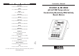
Instruction Manual SALES AND TECHNICAL SERVICE CONTACTS Australia: Tel. (03) 9769.0666 • Fax (03) 9769.0699 HI 4521 & HI 4522 China: Tel. (10) 88570068 • Fax (10) 88570060 pH/mV/ISE/Temperature/ Conductivity/Resistivity/TDS/Salinity Bench Meters Egypt: Tel. & Fax (02) 2758.683 Germany: Tel. (07851) 9129-0 • Fax (07851) 9129-99 Greece: Tel. (210) 823.5192 • Fax (210) 884.0210 Indonesia: Tel. (21) 4584.2941 • Fax (21) 4584.2942 Japan: Tel. (03) 3258.9565 • Fax (03) 3258.9567 Korea: Tel. (02) 2278.
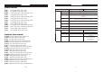
OTHER ACCESSORIES HI 710005/8 HI 710006/8 ChecktempC HI 76404N HI 8427 HI 931001 HI HI HI HI 76312 7662-T 92000 920010 Voltage adapter from 115 VAC / 12 VDC 800 mA (USA plug) Voltage adapter from 230 VAC / 12 VDC 800 mA (European plug) Pocket-size thermometer (range –50.0 to 150.0 ºC) Electrode holder pH and ORP electrode simulator with 1 m (3.3') coaxial cable ending in female BNC connectors pH and ORP electrode simulator with LCD and 1 m (3.
ORP ELECTRODES HI 3131B Glass-body, refillable, combination platinum ORP electrode. Use: titration. Dear Customer, Thank you for choosing a Hanna Instruments product. This manual will provide you with the necessary information for correct use of the instrument. Please read this instruction manual carefully before using the instrument. If you need additional technical information, do not hesitate to e-mail us at tech@hannainst.
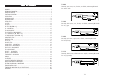
TABLE OF CONTENTS WARRANTY ...................................................................................................................................... 3 PRELIMINARY EXAMINATION .............................................................................................................. 5 GENERAL DESCRIPTION ...................................................................................................................... 6 FUNCTIONAL DESCRIPTION ...............................................
HI 2031B Glass-body, semimicro, conic, refillable, combination pH electrode. Use: semisolid products. HI 1332B Plastic-body, double junction, refillable, combination pH electrode. Use: general purpose. PRELIMINARY EXAMINATION Remove the instrument from the packing material and examine it carefully to make sure that no damage has occurred during shipping. If there is any damage, notify your dealer or the nearest Hanna Service Center.
GENERAL DESCRIPTION HI 4521 and HI 4522 are professional bench meters with color graphic LCD for pH, ORP (Oxidation Reduction Potential), ISE (HI 4522 only), conductivity, resistivity, TDS, salinity and temperature measurements. The display can be configured as a single channel or dual channel display in various modes: Basic information only, GLP information, Graph and Log History mode.
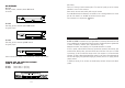
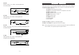
FUNCTIONAL DESCRIPTION pH ELECTRODES All electrodes part numbers ending in B are supplied with a BNC connector and 1 m (3.3') cable, as shown below: HI 4521/4522 DESCRIPTION FRONT PANEL HI 1043B Glass-body, double junction, refillable, combination pH electrode. Use: strong acid/alkali. HI 1053B Glass-body, triple ceramic, conic shape, refillable, combination pH electrode. Use: emulsions. REAR PANEL HI 1083B Glass-body, micro, Viscolene, non-refillable, combination pH electrode.
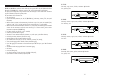
To enter/exit calibration mode; HI HI HI HI To select the desired measurement mode, pH, mV, Rel mV, ISE (HI 4522 only), Conductivity, Resistivity, TDS, Salinity; ELECTRODE STORAGE SOLUTIONS To enter Setup (System Setup, pH Setup, mV Setup, ISE Setup (HI 4522 only), Conductivity Setup, Resistivity Setup , TDS Setup or Salinity Setup) and to access Log Recall function; HI 70300L Storage Solution, 500 mL bottle HI 80300L Storage Solution in FDA approved bottle, 500 mL KEYBOARD DESCRIPTION FUNCTION KEYS
ACCESSORIES SPECIFICATIONS pH BUFFER SOLUTIONS HI HI HI HI HI HI HI HI HI HI HI HI HI 6001 6003 8004L 6004 8006L 6068 8007L 6007 6091 8009L 8010L 6010 6124 pH pH pH pH pH pH pH pH pH pH pH pH pH 1.679 Buffer Solution, 500 mL bottle 3.000 Buffer Solution, 500 mL bottle 4.01 Buffer Solution in FDA approved bottle, 500 mL 4.010 Buffer Solution, 500 mL bottle 6.86 Buffer Solution in FDA approved bottle, 500 mL 6.862 Buffer Solution, 500 mL bottle 7.01 Buffer Solution in FDA approved bottle, 500 mL 7.
HI 4521 0.000 to 9.999 µ S/cm 10.00 to 99.99 µ S/cm 100.0 to 999.9 µ S/cm 1.000 to 9.999 mS/cm 10.00 to 99.99 mS/cm 100.0 to 1000.0 mS/cm Ra nge Cond uctivity HI 4522 Resolution 0.001 µ S/cm 0.01 µ S/cm 0.1 µ S/cm 0.001 mS/cm 0.01 mS/cm 0.1 mS/cm Accura cy ±1% of rea d ing (±0.01 µ S/cm) Cell consta nt 0.0500 to 200.
mV / pH / ISE CHANNEL SYMPTOMS Slow response/excessive drift. HI 4521 PROBLEM D irty pH electrode. Readings fluctuate up Clogged/dirty junction. and down (noise). L ow electrolyte level (refillable electrodes only). Clean the electrode. Refill with fresh solution (for refillable electrodes only). The LCD displays "-----" Out of range in the during measurements appropriate scale. (pH, mV, mV Rel or ISE ). Make sure the sample is in the specified range. Recalibrate.
OPERATIONAL GUIDE POWER CONNECTION TROUBLESHOOTING GUIDE CONDUCTIVITY / RESISTIVITY / TDS / SALINITY CHANNEL Plug the 12 VDC adapter into the power supply socket. Note: These instruments use non volatile memory to retain the meter settings, even when unplugged. ELECTRODE AND PROBE CONNECTIONS For pH or ORP measurements connect a pH / ORP electrode with internal reference to the BNC connector located on the rear panel of the instrument.
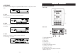
For AmpHel ® electrodes: CHANNEL SELECTION If the electrode does not respond to pH changes, the battery run down and the electrode should be replaced. • Press while in Measure mode to access channel selection menu. Four available options will be displayed: Channel 1, Channel 2, or multi-channel with the first or the second channel focused. The “Choose Channel Configuration” message is displayed in the Reminder messages area when is pressed.
DISPLAYING MODES ELECTRODE CONDITIONING & MAINTENANCE For each measurement mode (pH, mV, Rel mV, Ion, Conductivity, Resistivity, TDS or Salinity) the following display configurations are available: Basic, Good Laboratory Practice (GLP), Graph and Log History. Basic Accessing this option, the measured value and its units are displayed on the LCD, along with the temperature value, temperature compensation mode, and minimal GLP data. To choose the Basic displaying mode: while in Measure mode.
PROBE CONDITIONING & MAINTENANCE MEASURE Rinse the conductivity probe with distilled water. Immerse the tip (bottom 4 cm /1½”) in the sample and stir gently for a few seconds. For a faster response and to avoid cross-contamination of the samples, rinse the probe with a few drops of the solution to be tested, before taking measurements. PERIODIC MAINTENANCE Inspect the probe and the cable.
Log History Accessing this option, last logged records will be displayed on the LCD. The log history list also contains the appropriate main parameter values, the logged temperature, the temperature compensation source / mode, as well as the records time stamp. To access the Log History displaying mode: while in Measure mode. The “Choose Display • Press Configuration” message will be displayed in the Reminder messages area. .
PC INTERFACE SYSTEM SETUP Data transmission from the instrument to the PC can be done with the HI 92000 Windows® compatible software (optional). HI 92000 also offers graphing and on-line help feature. Data can be exported to the most popular spreadsheet programs for further analysis. HI 4521 and HI 4522 instruments have two available serial interfaces: RS232 and USB. The desired serial interface can be selected from the settings window of the HI 92000 software.
To set the Beeper: • Use or to select the Beeper option. • Press and use or to highlight the desired beeper associated parameter you want to modify. • Press and use beeper status option. • Press or to highlight the to confirm your selection and return to the Beeper menu or press to return without changing. highlighted lot. The “Please wait...” message will be displayed on the LCD for a short period. The user customised report will be displayed on the LCD.
set as Direct/AutoHold in order to use this logging mode. To log data using this mode: To set the GLP Data: • Use while in Measure mode to start the logging session. The logged values are only the ones • Press frozen on the LCD, after was pressed and the stability criterion reached. • To store another frozen value, press to return to normal logging mode and then again. or / .
• Press to confirm your selection. Use and then use and to modify the value with (for Set Date and Time option). For the or other two options press The “Logging”, sampling period and “AutoHold” indicators will be displayed on the LCD. / • To store another frozen value, press • To stop the logging session, press again. / . to confirm your selection and select one of the displayed formats with or . • Press to confirm your selection and return to the Date & Time options.
• To stop the logging session, press / . The Log Save screen will display thelog lot ID, the settable log interval / sampling: • Press to adjust the log interval and/or the log to save the current log in sampling or press the displayed format. • Press To select the Language: • Use to enter log interval edit menu and use or to adjust the logging start-stop to save the time or the log sampling. Press current value and use next / previous parameter.
Meter Information This option provides general information about the instrument serial number (each instrument has an unique identification serial number), the software version and the factory calibration date and time (for mV, conductivity and temperature). Note: All the instruments are factory calibrated for mV, conductivity and temperature.
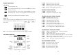
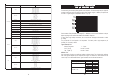
TEMPERATURE CALIBRATION p H SETUP The temperature user calibration menu can be accessed at the meter startup by pressing simultaniously three keys as in the below drawing: The pH Setup menu allows the user to set the parameters associated with pH measurement and calibration. Accessing pH Setup while in Measure mode and then • Press select pH range for the desired channel. • Press and then to to access pH Setup menu.
Note: The saved profile will automatically become the current profile. Load Profile To load one profile: • Use or • Press and use Load Profile option. PRACTICAL SALINITY SCALE (UNESCO 1978) According to the definition, salinity of a sample in psu (practical salinity units) is calculated using the following formula: to select the Profile option. or to highlight the • Press . A list with all customised profiles will be displayed on the screen.
SALINITY CALIBRATION Salinity calibration is a one-point calibration procedure at 100.0% NaCl. Use the HI 7037L calibration solution (sea water solution) as a 100% NaCl standard solution. To enter salinity calibration: • Set the meter for salinity range; • Select the Percent Scale (see Salinity Setup section); • Rinse the probe with some of the calibration solution or deionized water; • Immerse the probe into HI 7037L solution. The sleeve holes must be completely submerged.
available buffers and you can choose the one used. Manual Selection – the desired pH buffer is manually selected from all available buffers, regardless of measured value. To select the Buffer Entry Type: • Use or TDS MEASURE MENT Make sure the TDS factor has been set before taking TDS measurements (see TDS Setup section). to select the Calibration option. • Press and use Buffer Entry Type option.
RESISTIVITY MEASURE MENT To edit the Custom Buffers: DIRECT MEASUREMENT To measure the resistivity of a sample using the Direct reading mode: • Press and then to select resistivity measure mode. • Select the Direct reading mode (see Resistivity Setup section). • Proceed as for the conductivity measurement (see Conductivity Measurement section). to select the Calibration option. or • Use Make sure the instrument has been calibrated before taking resistivity measurements.
Calibration Reminder In order to have accurate readings, the instrument must be calibrated frecquently. Three options are available for the calibration reminder: Daily, Periodic or Disabled. To set the Calibration Reminder: • Use or to select the Calibration option. • Press and use Calibration Reminder option. or to highlight the • Press and use desired option. or to highlight the • Press to confirm your selection or press cancel operation.
DIRECT/USP MEASUREMENT In this measure mode the user can check for ultra pure water using the United States Pharmacopeia standard (USP <645>). This USP standard consists of three stages (one in-line and two off-line tests) as following: Stage 1 - this is an in-line test. To perform this test: • Measure the temperature of the water and the uncompensated conductivity readings. The measurement may be performed in a suitable container or as in-line measurement.
Edit Sample ID This option allows the user to edit the sample ID. Note: If the ID Increment Mode is set to None, the sample ID can be set alphanumerically, otherwise it can be set only numerically. To edit the Sample ID: or to select the Sample ID option. • Use and use • Press Edit Sample ID option. or to highlight the to confirm your selection.
• Insert and rinse the probe in the first beaker in order to decontaminate it; • Insert the probe in the second beaker; • Tap the probe repeatedly to remove any air bubbles that may be trapped inside the sleeve. ; • Enter in calibration mode by pressing • Wait to stabilize; • When the automatic standard recognition is selected, the calibration point will be automatically selected from the Hanna standard list (84 µS, 1413 µS, 5.0 mS,12.88 mS, 80.0 mS, 111.8 mS).
after the logging session was started. To set the Logging Type: • Use or CONDUCTIVITY CALIBRATION to select the Log option. and use • Press Logging Type option. or to highlight the and use • Press desired option. or to highlight the • Press to confirm your selection or press cancel operation. to It is recommended to calibrate the instrument frequently, especially if high accuracy is required. The conductivity range should be recalibrated: • Whenever the conductivity probe is replaced.
Clear Calibration Accessing this option, the existent salinity calibration (Percent Scale) can be cleared. To clear calibration: • Use to highlight the Clear Calibration option. or • Press to clear calibration. A pop-up menu will be displayed to ask for confirmation. • Press to confirm or press to cancel operation. Sampling Period This option allows the user to select the desired sampling period for automatic logging type. To set the Sampling Period: or to select the Log option.
Alarm This option allows the user to edit the alarm settings: Alarm State and Alarm Limits. If the Alarm option is enabled, a continuous double beep will be heard, along with the “Alarm” indicator blinking on the LCD, each time the set limits in Measure mode are exceeded. Alarm State Three modes are available for the Alarm State option: Disabled – the alarm will be disabled. Inside Limts – the alarm will notify the user when the measured value is inside the set limits.
TDS factor Confirmation is enabled, press or With this option the user can set the TDS factor. • Use • Press or to highlight the TDS options. to confirm your selection and use or to increase / decrease the value. • Press to confirm your selection or press cancel operation. to to accept the modified option, to return to the editing mode. Otherwise, the modified option is saved automatically.
mV SETUP TDS SETUP The mV Setup menu allows the user to set the parameters associated with mV and Relative mV measurements. Accessing TDS Setup Accessing mV Setup • Press while in Measure mode and then or to select mV / mV Rel range. • Press and then or • Press while in Measure mode and then select TDS range. • Press to access mV Setup menu. To access a mV Setup option: • Use The TDS Setup menu allows the user to set the parameters related to the TDS measurement.
Temperature - see Conductivity Setup section. ISE SETUP (HI 4522 only only)) Units The user can choose between Ohm, KOhm, MOhm, AutoRanging measuring modes. To select the units: • Use or to highlight the Units option. • Press to confirm and then use to highlight the desired unit. • Press to confirm or press or The ISE Setup menu allows the user to set the parameters regarding ISE measurement and calibration. These parameters can be set specifically for each channel.
Analyte Addition This method is similar to the Known Addition method, with the difference that an aliquot of sample is added to a standard of known concentration. The sample and standard contain the same ion to be measured. The ion concentration is then calculated using the difference in mV potential. Analyte Subtraction In the Analyte Subtraction method an aliquot of sample is added to a standard of known concentration, reacting with the ion to be measured.
Alarm This option allows the user to define two alarm limits. Alarm State The following options are available: Disabled – the alarm will be disabled. Inside Limits – the alarm will notify the user when the measured value is inside the preset limits. Outside Limits – the alarm will notify the user when the measured value is outside the preset limits. To set the alarm state: • Use or to highlight the Alarm State option.
To set the Electrode Type: • Use or to select the Electrode Type option. • Press and use or to select the desired standard ISE or a custom one from the list. For standard ISE: • Press to visualize the Ion constants and then press at any time to exit Ion Constants view mode. • Press to confirm your selection and return to ISE Setup options. For custom ISE: • Press Sampling Period This option allows the user to select the desired sampling period for automatic logging.
Log This option allows the user to edit the settings related to the logging feature, as following: Logging Type Three logging types are available: Automatic, Manual and AutoHold. Automatic logging - the readings are logged automatically at constant time intervals (see Sampling Period option). Manual logging ( log on demand)- the readings are logged each time is pressed. AutoHold logging - the readings are logged automatically at each auto-hold event occured.
Isopotential Point This option allows the user to edit the isopotential point of the electrode used for ion measurements. The ion selective electrodes have different isopotential points. If temperature compensation is desired for the ion measurements, the isopotential point value is absolutely necessary. The isopotential point is always edited in ppm (mg/L) units. To set the Isopotential Point: • Use or to select the Isopotential Point option. and use or • Press decrease the isopotential point value.
Clear Calibration Accessing this option, the existent conductivity calibration can be cleared. If the calibration is cleared, another calibration has to be performed. To clear calibration: or to highlight the Clear Calibration option. • Use • Press to clear calibration. A pop-up menu will be displayed asking for confirmation. • Press to confirm or press to escape without saving and return to the Calibration options.
Three buffer entry types are available: Automatic, Semiautomatic and Manual Selection. The default option is Manual Selection. To calibrate the instrument using Manual Selection buffer entry type: • Press . If the instrument was calibrated before and calibration was not cleared, the old . After 10 seconds, will no longer be available calibration can be cleared by pressing from calibration screen.
Calibration Points The user can choose between Single Point and Multi Points calibration. To set the calibration points: or to highlight the Calibration Points • Use option. • Press to confirm your selection and then use or to choose the desired option. • Press to confirm your selection or press cancel operation. to Cell constant manual editing: The conductivity probe can also be calibrated by entering the cell constant value.
• Unrecognized buffer. Please check the buffer or the buffer list (for Semiautomatic and Automatic buffer entry type): this message appears if the current buffer value is not close to any of the buffers from the buffer list/group. Check if the current buffer is present in the buffer list or the appropriate buffer group was selected. • The current buffer was already calibrated.
Temperature Unit The user can choose from the Celsius, Fahrenheit or Kelvin temperature units. To set the temperature unit: or to highlight the Temperature Unit • Use option. • Press and then use or to select Celsius, Fahrenheit or Kelvin degrees unit. • Press to confirm your selection or press to cancel operation. Reference Temperature (only for Linear or Non-Linear temperature compensation) To set the reference temperature: • Use or to highlight the Reference Temperature option.
Outside Cal Range feature warns the user if the current reading is out of the calibrated area. The calibrated area is that part of the pH range in which the calibration point assures an accurate reading. If the reading is taken out of the calibration area, the “Outside Cal Range” message will start blinking on the LCD. The calibrated area is calculated in according with the pH resolution used during the reading.
Temperature Compensation The user can choose from the following options: Linear - the meter will compensate automatically the conductivity using the following formula: mV & Relative mV MEASURE MENT S MEASUREMENT mV/ORP MEASUREMENTS Oxidation-reduction potential (ORP) measurements provide the quantification of the oxidizing or reducing power of the tested sample. To correctly perform a redox measurement, the surface of the ORP electrode must be clean and smooth.
Relative mV MEASUREMENTS To measure the Relative mV of a sample: and then to enter Relative mV • Press Measure mode. • The instrument will display the measured Relative mV value on the LCD, together with a short GLP information about the last calibration or “Not Calibrated” message if no Rel mV calibration was performed (no Rel mV offset set).
Delete Profile To delete one of the existing profiles: • Use or to select the Profile option. and use • Press Delete Profile option. or ISE CALIBRATION (HI 4522 only) to highlight the • Press the screen. . A list with all customised profiles will appear on • Use or to select the desired profile and press . • Press to return to the previous menu. For greatest accuracy, it is recommended to calibrate the instrument frequently.
Two standard entry types are available: ManualSelection and Custom Standard. The default option is Manual Selection. A. To calibrate the instrument using Manual Selection standard entry type: • Press . If the instrument was calibrated before and calibration was not cleared, the old calibration can be Save Current Profile To save the current profile: • Use or to select the Profile option. cleared by pressing . After 10 seconds, will no longer be available.
Conductivity SETUP The Conductivity Setup menu allows the user to set the parameters related to the conductivity measurement. Accessing Conductivity Setup • Press while in Measure mode and then select the Conductivity measure mode. • Press and then Setup menu. To access a conductivity setup options: • Use or to to access Conductivity to highlight the desired option. • Press to access the selected option or to exit setup. The following is a detailed description of the Conductivity Setup option screens.
is significant. If this message is displayed, check if you have selected the appropriate calibration standard.to be tested. Allow time for the electrode to stabilize. • Wrong new slope. Please check the standard solution: this message appears if the current slope exceeds slope window (50% to 120% of default slope for the corresponding ion charge - see ISE Theorysection for details). Recalibrate the instrument using fresh standards. • Wrong old slope.
ISE MEASUREMENT (HI 4522 only) where: CSAMPLE - the sample concentration; CSTD - the standard concentration; VSAMPLE - the sample volume; VSTD - the standard volume; and VT = VSAMPLE + VSTD ∆E - the difference of potential from the electrode; S - the electrode slope, determined in a previous calibration; f - the stoichiometric ratio between sample and standard; Example 1 You have sulfide samples and you are adding Ag+. The reaction is: One mole sulfide sample reacts with 2 moles silver standard (f = ½).
, the “AutoHold” indicator • The measured concentration value will be displayed on the LCD. If pressing will start blinking on the LCD until the stability criterion is reached. The concentration value will be frozen on the LCD, along with “AutoHold” indicator. • To return to normal Measure mode press . Note: If the reading is out of range, “-----” will be displayed on the LCD. Note: Press Actual samples that are more concentrated have much smaller activity coefficients ( <1).
ISE THEORY An Ion Selective Electrode (ISE) is an electrochemical sensor that changes voltage with the activity or concentration of ions in solutions. The change in voltage is a logarithmic relationship with concentration and is expressed by the Nernst equation: • Press to change the desired method parameters as indicated in the first step of the method. • Press to take the second mV reading. • When the reading is stable, press results will be displayed on the LCD.
results will be displayed on the LCD. • Press • If pressing to log the current results into a ISE Method • Press to return to ISE Measure mode. Report or press Note: Press • If pressing , the method parameters can be changed and the sample concentration will be recalculated. • Press , the method parameters can be changed and the sample concentration will be recalculated. to start another measurement. at any time to stop the measurement and return to ISE Measure mode.