HI 504901 GSM Supervisor Instruction Manual
TABLE OF CONTENTS WARRANTY . . . . . . . . . . . . . . . . . . . . . . . . . . . . . . 5 PRELIMINARY EXAMINATION . . . . . . . . . . . . . . . . . . 6 GENERAL DESCRIPTION . . . . . . . . . . . . . . . . . . . . . 6 MAIN FEATURES . . . . . . . . . . . . . . . . . . . . . . . . . . . 7 FUNCTIONAL DESCRIPTION . . . . . . . . . . . . . . . . . . 8 MECHANICAL DIMENSIONS . . . . . . . . . . . . . . . . . . 9 TECHNICAL DATA . . . . . . . . . . . . . . . . . . . . . . . . . 10 SAFETY INFORMATION . . . . . . . . . .
SMS DELIVERY . . . . . . . . . . . . . . . . . . . . . . . . . . . Alarm SMS . . . . . . . . . . . . . . . . . . . . . . . . . . . . . Information SMS . . . . . . . . . . . . . . . . . . . . . . . . . Digital Output Control . . . . . . . . . . . . . . . . . . . . . 35 35 40 45 PC COMMUNICATION . . . . . . . . . . . . . . . . . . . . . Local Communication . . . . . . . . . . . . . . . . . . . . . Remote Communication . . . . . . . . . . . . . . . . . . . . PC Communication Protocol . . . . . . . . . . . .
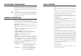
PRELIMINARY EXAMINATION Remove the instrument from the packing material and examine it carefully to make sure that no damage has occurred during shipping. If there is any noticeable damage, notify your Dealer or the nearest Hanna Customer Service Center immediately. Note Save all packing materials until you are sure that the instrument functions correctly. Any damaged or defective items must be returned in their original packing materials together with the supplied accessories.
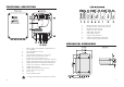
FUNCTIONAL DESCRIPTION 1. 2. 3. 4. 5. 6. 7. 8. 9. RS232 serial port, channel #1, red LED. RS232 serial port, channel #2, red LED. RS485 serial port red LED. Digital input port red LED. SMS enable green LED. SMS disable red LED. Digital output yellow LED. Cellular signal strength green LED’s. Cellular operating status yellow LED. MECHANICAL DIMENSIONS 1. 2. 3. 4. 5. 6. 7. 8. 9. 10. 11. 12. 13. 14. Backup battery (rechargeable, sealed lead-acid, 12V / 0.8Ah). On board battery connector.
TECHNICAL DATA SAFETY INFORMATION Max output power 2 W for EGSM900; 1 W for GSM1800/1900 SIM interface 3V type SIM card Antenna Dual-band antenna (900/1800/1900 MHz) RS232 channels towards instruments For connection of an instrument with RS232, baud rate up to 9600 (limited by the instrument) RS485 channel towards instruments For connection of all instruments with RS485 in the same bus; baud rate up to 9600 Digital input channel Supporting mechanical relays or open-collector outputs Digital output
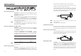
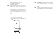
from 5 to 30 V is applied or when it is disconnected. This input can come from a relay contact or from an open collector output (for example from a PLC). Connect the positive pole of an external power supply to the positive DIG-IN terminal; connect a command relay between the negative pole of the external power supply and the negative DIG-IN (see also below diagram).
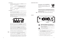
Specifications: The RS485 standard is implemented in HI504901 interface with the following characteristic: Data rate: up to 9600 (selected while configuring the interface through HI504901SW software) Communication: bidirectional Half-Duplex Line length: up to 1.2 Km typical, with 24 AWG cable Loads: up to 32 typical Internal termination: none Connections: The connections for the provided 2-pin RS485 terminal are as shown on the below diagram.
Note Note 6. connect the battery cable to the connector; 7. connect the interface to the mains; 8. turn ON the power switch. Pay attention that the battery cable is correctly connected to the battery connector, otherwise an alarm SMS will be sent immediately after the start-up procedure (see “Fault Condition” section for details). If the interface is powered on immediately after a battery substitution, it is possible that an alarm SMS of “Battery failure” is sent.
START-UP IDLE STATE Note 18 Turn ON the power switch (#14 on page 8): the red SMS disable LED lights up and will stay in this state until the start-up procedure ended and the idle mode is entered. During start-up procedure the Real Time Clock (RTC) is checked to control if a reset occurred since last software initialization. In this case, the RTC is initialized with the default date and time 01/01/2000 - 00:00. An EEPROM reset does not affect the RTC settings.
Note Also the digital output status LED is updated with the current status of the digital output contact. The digital output contact status can be changed by the user only by sending the proper SMS to the interface. The below table shows the digital output LED indication depending on the digital output status: Note LED Status Meaning Digital Output (yellow) OFF ON Dig.output contact open Dig.
INTERFACE CONFIGURATION The HI504901 supervisor is not provided with keyboard or display for user interfacing purpose. For first installation and for successive changes of the system configuration, it is necessary to use the HI504901SW Windows® compatible application software provided with the instrument. APPLICATION SOFTWARE INSTALLATION To install the HI504901 configuration software on the computer, it is necessary a 3.5’’ drive. Insert the disk #1 in the floppy disk driver, execute setup.
Note In the “Advanced Settings” section it is possible to give to the modem connected to the PC a particular configuration for the initialization string and the dial string. Note that in the most common cases the default setting can be used. On “Serial Communication Port” section select the COM port to which the modem is connected.
software advises the user with warning messages if some error occurs on the interface. The following fault conditions can be detected by HI504901SW: • “Error on cellular phone found”: warning for generic error on cellular phone, e.g. cellular phone not network registered, SIM card missing, no network coverage, cellular phone not answering, etc. • “Wrong cellular PIN code”: PIN code on HI504901 is not correct.
Note 15 days, 7 days and 1 day before the expiration date, warning SMS messages will be sent to the programmed number(s). It is useful to enable this feature in case of a rechargeable SIM card, and disable it if an unlimited credit card or a special rechargeable SIM card is used. If the feature is enabled, it is necessary to insert a date to proceed with the configuration. SMS options: • On “Repeated SMSs” field it is possible to set the number of repeated SMSs to be sent.
Note If the SIM card PIN number is longer than 4 digits, it has to be changed before using it in the HI504901 interface. To do this, insert the SIM card in a cellular phone and change the old PIN number with a new one with value from 0000 to 9999, while paying attention to remember the new code (please refer to the cellular phone instruction manual for the correct procedure).
Note Note To enable one RS485 instrument, all the three previous options (instrument name, baud rate and RS485 address) must be set. • Messages options: to set the alarm message options, click on the “Message Options” button. This feature depends on the instrument previously selected and it is only available for HI504 and HI504910 devices (see also the “HI504 and HI504910 Message Options” section).
Note Note Note open the digital output contact. If the digital output control is enabled, when an information will be requested to HI504901, an SMS with the digital output status will be sent. By disabling this option, it will not be possible to set the digital output status and no information SMS about the digital output will be sent. If the digital output management is disabled, the digital output will be automatically opened, even if it was previously closed.
only active alarms; when all active alarms can not be sent within one SMS (the maximum number of characters for an SMS is 160), more than one message will be sent, each one having as header the label “Alarms#p/#t:” with the indication of the progressive alarm SMS number (#p) and the total number of alarm SMSs (#t) that are going to be sent for the instrument. The label is a text string correspondent to the instrument model with active alarm(s).
some parameters for serial communication (as baud rate or device RS485 address) are not correct (parameters values probably are not the same on HI504901 and meter side; see “Interface configuration” section).
got from the controlled instruments, and could be requested, for example, after an alarm message regarding an error which should close without any intervention. The user could also want to be informed about the values of the measured magnitudes or current devices status. The information messages can be requested: 1.
list of all active alarms with the previously described format (see section “Alarms for HI8001 and HI8002 controllers”).
Also a cellular error indication is given by interface: green and red LEDs disable/enable blink together. To disactivate this error and restore the SMS service, it is necessary to recharge the SIM card credit. Note Note 44 Every time a recharge of the cellular module SIM card is performed, the corresponding expiration date has to be manually updated with the application software HI504901SW (see “Interface configuration” section).
nection. To connect the HI504901 supervisor to PC use an HI920010 cable. Plug the connectors, one to the supervisor RS232 auxiliary connector (PC config port), and the other one to a serial port of the PC. PC COMMUNICATION HI504901 interface can act as a gateway for a connection through a remote computer.
PC COMMUNICATION PROTOCOL Even if it is strongly recommended to use HI92500 software to establish local or remote connections between HI504901 and a PC, it is possible to try also without HI92500 by building the application software for communication session management (i.e. session establishment, serial port channel selection and session termination). It is necessary to issue to the interface towards PC some simple commands accomplishing with the protocol implemented on HI504901.
select which channel and baud rate the interface uses for communicating with the target device (i.e. the baud rate used by interface during polling procedure and set during last interface configuration). To do this, the CNR command with the proper values (channel N and rate R) has to be sent to cellular phone interface. For example, if target device is attached on RS232-1 port and its communication rate is 2400 bps, then the command C0B must be issued.
LEDs STATUS DURING PC COMMUNICATION SESSION Following is a table with all possible status of HI504901 LEDs during a PC communication session: LED RS232 channel # (red) RS485 channel (red) Digital input (red) SMS enable (green) SMS enable (red) Digital output (yellow) Cell signal quality (2 green LEDs) Cell status (yellow) 52 Meaning PC communication in progress with another channel or not yet channel selection made by remote PC Blinking Communication session in progress between remote PC and this chann
tion will be given by the interface: FAULT CONDITIONS & SELFTEST PROCEDURES HI504901 is provided with some selftest procedures to prevent interface problems. The below fault conditions may be detected by the software: • EEPROM data error • Cellular phone error • Battery test failure If a problem is found, HI504901 gives to the user a “visual” indication through green and red LEDs for SMS sending enable/disable (also for battery test failure an alarm SMS is submitted to the programmed number(s)).
LED INDICATORS Find here below a brief explanation of all possible LEDs indications of HI504901 interface. RS232 CHANNEL# LED This red LED keeps indication about device connected to the RS232 channel#.
ERRORS PRIORITY HI504901 is provided with some selftest procedures and related “visual” LED indications when some of these tests failed, in order to make the user understand the interface related problem (see “Fault conditions and selftest procedures” section). Only two LEDs (green and red LEDs for SMS sending enable/ disable) are available to give information to the user about active errors, and no more than one can be shown at the same time.
• During remote interface configuration attempt the HI504901SW software can not connect to the HI504901 interface. Possible causes Solutions Modem on PC is turned off. Turn on the modem and try again. SIM card on HI504901 is not able to Change the SIM card with one enabled make data calls. for data calls. Note: Some SIM cards can be used both for data and voice calls. Please check the network operator for further details. Install HI504901 interface in a place with good HI504901 interface is out of coverage.
• Can not receive alarm SMSs regarding digital input port. Possible causes Wiring not correctly performed. HI504901 not configured to send alarm SMSs for digital input port status. Current status of digital input port does not match with the one set on HI504901 interface. SMS sending disabled through external switch. Solutions Check if wires on digital input port are correctly connected to HI504901 supervisor. Run HI504901SW application software and configure HI504901 for communication with remote device.
APPENDIX CE DECLARATION OF CONFORMITY RS232 AUXILIARY PORT HI504901 is provided with an auxiliary RS232 port (D-Sub 9-pole female plug) for connection to a local PC using an HI920010 Hanna cable. If the provided HI920010 Hanna cable is too short for your application, it is possible to make a longer communication cable (up to 15 m long) by following the below table for pin connections.
USER NOTES 66 67
TECHNICAL SERVICE CONTACTS Australia: Tel. (03) 9769.0666 • Fax (03) 9769.0699 China: Tel. (10) 88570068 • Fax (10) 88570060 Egypt: Tel. & Fax (02) 2758.683 Germany: Tel. (07851) 9129-0 • Fax (07851) 9129-99 Greece: Tel. (210) 823.5192 • Fax (210) 884.0210 Indonesia: Tel. (21) 4584.2941 • Fax (21) 4584.2942 Japan: Tel. (03) 3258.9565 • Fax (03) 3258.9567 Korea: Tel. (02) 2278.5147 • Fax (02) 2264.1729 Malaysia: Tel. (603) 5638.9940 • Fax (603) 5638.9829 Singapore: Tel. 6296.7118 • Fax 6291.