HI 504903 GSM Supervisor Instruction Manual
TABLE OF CONTENTS WARRANTY . . . . . . . . . . . . . . . . . . . . . . . . . . . . . . 5 PRELIMINARY EXAMINATION . . . . . . . . . . . . . . . . . . 6 GENERAL DESCRIPTION . . . . . . . . . . . . . . . . . . . . . 6 MAIN FEATURES . . . . . . . . . . . . . . . . . . . . . . . . . . . 7 FUNCTIONAL DESCRIPTION . . . . . . . . . . . . . . . . . . 8 MECHANICAL DIMENSIONS . . . . . . . . . . . . . . . . . . 9 TECHNICAL DATA . . . . . . . . . . . . . . . . . . . . . . . . . 10 SAFETY INFORMATION . . . . . . . . . .
Dear Customer, Thank you for choosing a Hanna Product. Please read this instruction manual carefully before using the instrument. It will provide you with the necessary information for correct use of the instrument, as well as a precise idea of its versatility. If you need additional technical information, do not hesitate to e-mail us at tech@hannainst.com. Information SMS . . . . . . . . . . . . . . . . . . . . . . . . . 35 Digital Output Control . . . . . . . . . . . . . . . . . . . . .
PRELIMINARY EXAMINATION Remove the instrument from the packing material and examine it carefully to make sure that no damage has occurred during shipping. If there is any noticeable damage, notify your Dealer or the nearest Hanna Customer Service Center immediately. Note Save all packing materials until you are sure that the instrument functions correctly. Any damaged or defective items must be returned in their original packing materials together with the supplied accessories.
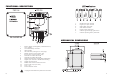
FUNCTIONAL DESCRIPTION 1. 2. 3. 4. 5. 6. 7. RS485 serial port red LED. Digital input port red LED. SMS enable green LED. SMS disable red LED. Digital output yellow LED. Cellular signal strength green LED’s. Cellular operating status yellow LED. MECHANICAL DIMENSIONS 1. 2. 3. 4. 5. 6. 7. 8. 9. 10. 11. 12. 13. 14. Backup battery (rechargeable, sealed lead-acid, 12V / 0.8Ah). On board battery connector. GSM module. LED indicators (see figure on next page).
TECHNICAL DATA SAFETY INFORMATION Max output power 2 W for EGSM900; 1 W for GSM1800/1900 SIM interface 3V type SIM card Antenna Dual-band antenna (900/1800/1900 MHz) RS485 channel towards instruments For connection of up to 31 HI142 temperature dataloggers on the same wire; baud rate fixed to 1200 bps (limited by the HI142 dataloggers) Digital input channel Supporting mechanical relays or open-collector outputs Digital output channel Open collector output, 5 mA / 30V max.
INSTALLATION DISABLE SMS (DISABLE) This input works as a digital input (see previous subsection) and allows to ignore active errors and suspend SMS sending during operations as start-up, maintenance, etc. RS232 AUXILIARY PORT Note Note HI504903 is provided with an auxiliary RS232 port (D-Sub 9-pole female plug) for connection to a local PC using an HI920010 Hanna cable.
To connect the subsequent dataloggers one to the other, use a cable with RJ11 plugs, made as explained in the “Appendix, section 2”. To terminate the line, plug on the last HI142 the termination key supplied with the HI504903 supervisor. All the instruments connected to the RS485 port are “slave” devices that are queried by the HI504903 supervisor.
Note Note To substitute battery, please follow below instructions: 1. turn off the HI504903: turn OFF the power switch and disconnect the interface from the mains; 2. remove the screws on the bottom of the two battery clips; 3. disconnect the battery cable from its connector; 4. substitute the old battery with a new one; 5. fix back the two girdles by tightening the screws; 6. connect the battery cable to the connector; 7. connect the interface to the mains; 8. turn ON the power switch.
Also the digital output status LED is updated with the current status of the digital output contact. The digital output contact status can be changed by the user only by sending the proper SMS to the interface. The below table shows the digital output LED indication depending on the digital output status: IDLE STATE The idle state is the normal operation state for the HI504903 supervisor.
Note SMS sending by the interface. SMS can be submitted by the HI504903 supervisor only if the SMS sending feature is enabled through an external switch (see further on for details); if the SMS sending is disabled, then no message will be sent upon alarm or fault condition on connected devices. To make the HI504903 queries the connected devices and sends SMS’s, it is necessary to configure the interface, otherwise no polling procedure can take place and no alarm notification will be given by the interface.
LOCAL CONFIGURATION The “Local” configuration is the only one allowed for the first configuration of HI504903 supervisor. This type of configuration takes place between the HI504903 device and a PC (placed near) with HI504903SW installed, through a serial cable connection. To connect the HI504903 supervisor to the PC, use an HI920010 cable. Plug one connector to the HI504903 device RS232 auxiliary connector (PC config port) and the other one to a serial port of the PC.
CONFIGURATION SETTINGS The setup procedure is divided into three different sections, displayed on three different folders inside the main window: • General Options Setting (see “General Options Setting”) • RS485 Options Setting (see “RS485 Options Settings”) • Digital I/O Options Setting (see “Digital I/O Options Settings”) Five buttons are available on the bottom of the window, which can be pressed for performing the following actions: “Update All” button: Press this button to send the complete configurati
upon a call from one of these phones. Valid values are numbers of a maximum of 20 digits, with the country code in front and without spaces or “+” symbol (e.g. for Italy 39335.....) Note At least a value for telephone number #1 must be inserted to proceed with configuration. Note The country code is necessary, otherwise HI504903 will not be able to send any SMS. Note The set phone number are not saved on the phonebook area of the SIM card.
Security options: • On “HI504903 Password” field it is possible to set the password for the HI504903 device. This password protects from unauthorized remote modem connection to one of the instruments connected to the cellular phone interface and from unauthorized remote configuration. This password does not block the local configuration of the instrument, i.e. no password is required to configure the HI504903 device with its application software through the serial cable. The password can be disabled.
mechanical relay or an open collector digital output can be connected to the HI504903 interface to trigger the sending of an alarm SMS message. The complete options list is: • Instrument enable: it is possible to enable this feature if an instrument is connected to the digital input simply by checking on the check-box.
SMS DELIVERY Note HI504903 is able to send SMSs to one (or two) cellular phone number(s). HI504903 can send two types of message: alarm SMSs (upon an alarm condition at least in one of the instruments connected to the interface) and information SMS (upon specific request from the user). To use the SMS feature, a SIM card able to make a voice call must be used.
Alarm SMSs specific to the interface Two alarm SMSs are provided to inform the user about troubles specific to the HI504903 interface, the first one concerning the internal backup battery status, the second one about mains power supply status. If a problem was found during last battery test (see “Fault conditions and selftest procedures” section), HI504903 issues the following alarm SMS: “Alarm! Battery test failure; Rem msg: ”.
For , and fields, please refer to the previous subsection. Find here below a complete list of available information (and coded notations) in the field for all HI142 devices connected to the HI504903 interface: • “Temp: ###.#C or F”: temperature reading in Celsius (“C”) or Fahreneit (“F”) unit, depending on last datalogger configuration.
sage “Maximum number of SMSs reached. Please check the HI504903 SIM charge level; Rem msg: ” will be sent by the instrument to the programmed cellular phone number(s). This particular situation is managed as an error occurrence and a confirmation is waited. When this happens, no more messages will be sent by the interface until the error is disactivated. Also a cellular error indication is given by interface: green and red LEDs disable/enable blink together.
nection. To connect the HI504903 supervisor to PC use an HI920010 cable. Plug the connectors, one to the supervisor RS232 auxiliary connector (PC config port), and the other one to a serial port of the PC. PC COMMUNICATION HI504903 interface can act as a gateway for a connection through a remote computer.
PC COMMUNICATION PROTOCOL Even if it is strongly recommended to use HI92140 software to establish local or remote connections between HI504903 and a PC, it is possible to try also without HI92140 by building the application software for communication session management (i.e. session establishment, serial port channel selection and session termination). It is necessary to issue to the interface towards PC some simple commands accomplishing with the protocol implemented on HI504903.
everything is works like a direct point-to-point connection (if the delay issues are excluded). No need to change baud rate value on PC side as modem buffers handle automatically the baud rate difference (remember that the baud rate must be kept at 9600 bps in remote communication on PC). Local PC connection closure The application software can close a local PC connection pulling down the DTR line of the serial port at any moment.
If cellular error is active, the following “visual” LED indication will be given by the interface: FAULT CONDITIONS & SELFTEST PROCEDURES HI504903 is provided with some selftest procedures to prevent interface problems.
LED INDICATORS Find here below a brief explanation of all possible LEDs indications of HI504903 interface. RS485 PORT LED This red LED keeps indication about devices connected to the RS485 port.
ERRORS PRIORITY HI504903 is provided with some selftest procedures and related “visual” LED indications when some of these tests failed, in order to make the user understand the interface related problem (see “Fault conditions and selftest procedures” section). Only two LEDs (green and red LEDs for SMS sending enable/ disable) are available to give information to the user about active errors, and no more than one can be shown at the same time.
• During remote interface configuration attempt the HI504903SW software can not connect to the HI504903 interface. Possible causes Solutions Modem on PC is turned off. Turn on the modem and try again. SIM card on HI504903 is not able to Change the SIM card with one enabled make data calls. for data calls. Note: Some SIM cards can be used both for data and voice calls. Please check the network operator for further details. Install HI504903 interface in a place with good HI504903 interface is out of coverage.
• Can not receive alarm SMSs regarding digital input port. Possible causes Wiring not correctly performed. HI504903 not configured to send alarm SMSs for digital input port status. Current status of digital input port does not match with the one set on HI504903 interface. SMS sending disabled through external switch. Solutions Check if wires on digital input port are correctly connected to HI504903 supervisor. Run HI504903SW application software and enable digital input on HI504903.
SECTION 2: CONNECTING HI142 TO HI142 APPENDIX SECTION 1: CONNECTING THE HI142 NETWORK TO HI504903 For connecting the first HI142 datalogger to the HI504903 interface, make a cable for both RS485 and power supply connections.
CE DECLARATION OF CONFORMITY Recommendations for Users Before using this product, make sure that it is entirely suitable for the environment in which it is used. Operation of this instrument in residential areas could cause unacceptable interferences to radio and TV equipment. To maintain the EMC performance of equipment, the recommended cables noted in the user's manual must be used. Any variation introduced by the user to the supplied equipment may degrade the instruments' EMC performance.
TECHNICAL SERVICE CONTACTS Australia: Tel. (03) 9769.0666 • Fax (03) 9769.0699 China: Tel. (10) 88570068 • Fax (10) 88570060 Egypt: Tel. & Fax (02) 2758.683 Germany: Tel. (07851) 9129-0 • Fax (07851) 9129-99 Greece: Tel. (210) 823.5192 • Fax (210) 884.0210 Indonesia: Tel. (21) 4584.2941 • Fax (21) 4584.2942 Japan: Tel. (03) 3258.9565 • Fax (03) 3258.9567 Korea: Tel. (02) 2278.5147 • Fax (02) 2264.1729 Malaysia: Tel. (603) 5638.9940 • Fax (603) 5638.9829 Singapore: Tel. 6296.7118 • Fax 6291.