Instruction Manual HI 88713 ISO Turbidity Meter w w w. h a n n a i n s t .
Dear Customer, Thank you for choosing a Hanna Instruments product. This manual will provide you with the necessary information for correct use of the instrument. Please read this instruction manual carefully before using the instrument. If you need additional technical information, do not hesitate to e-mail us at tech@hannainst.com or see the back side of this manual for our worldwide sales and technical service contacts. This instrument is in compliance with directives.
The HI 88713 Turbidity bench meter features G.L.P. (Good Laboratory Practice) functions that allow traceability of the calibration conditions. The last calibration points as well as time and date The HI 88713 Turbidity bench meter has a user-friendly interface with an easy to understand, graphical LCD. Comprehensive contextual help is available at a simple key press. All messages and help screens are available in several languages.
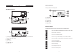
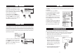
FUNCTIONAL DESCRIPTION DISPLAY DESCRIPTION The display contains the following fields: INSTRUMENT DESCRIPTION 1) 2) 3) 4) 5) Current time Functional keys Selected mode Measuring units Measured value KEYPAD DESCRIPTION The keypad contains 8 direct keys and 3 functional keys with the following functions: Press to perform the function displayed above it. The function are screen releated. ESC RANGE 1) 2) 3) 4) 5) 6) Liquid Crystal Display (LCD).
SPECIFICATIONS FNU mode Range Resolution Accuracy FAU mode Range Resolution Accuracy NTU ratio mode Range Resolution Accuracy NTU non ratio mode Range Resolution Accuracy Range selection Repeatibility Stray Light Light Detector Method Measuring mode Turbidity Standards Calibration Light Source Lamp life Display LOG Memory Serial Interface Environment Power supply Dimensions Weight 0.00 to 9.99; 10.0 to 99.9; 100 to 1000 FNU 0.01; 0.1; 1 FNU ±2% of reading plus straylight 10.0 to 99.9; 100 to 4000 FAU 0.
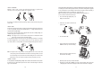
CUVETTE PREPARATION Whenever a cuvette is used, it must be clean inside and outside. When it is placed into the instrument, it must be dry outside, completely free of fingerprints or dirt. To further reduce the effect of glass imperfections, the cuvette can be indexed and use this new index as the position mark. For indexing one cuvette or matching multiple cuvettes, the continuous reading mode is suggested. In this mode multiple successive readings are taken without turning off the lamp.
• Mark this position on the white band at the top of the cuvette with a water resistant pencil. • Always use this position to align the cuvette with the mark on the cuvette holder. MATCHING MULTIPLE CUVETTES Precise measurements require the use of a single cuvette. If it is not possible, cuvette selection and matching must be performed before taking measurements. In order to match multiple cuvettes follow the next steps: • Fill multiple cuvettes with high quality water (<0.1FNU) up to the 10 mL mark.
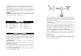
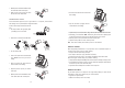
• Use of an ultrasonic bath; • Heating the sample. Sometimes it is necessary to combine two or more methods for efficient air bubble removal. Note: Each method can alter the sample turbidity, if misused, so they have to be used with caution. APPLICATION OF VACUUM Vacuum works by decreasing the atmospheric pressure. The bubbles from the solution come out to the surface. Application of vacuum is a very simple procedure andany vacuum can be used. The simplest equipment is a syringe and a rubber stopper.
RANGE SELECTION The HI 88713 bench-top Turbidity meter has four measuring modes: FNU, FAU, NTU Ratio and NTU Non Ratio. When the instrument is in the main screen, the selected mode is displayed in the right side of the LCD, on the message line. To change the mode, press the RANGE key. When the display shows the Change mode screen, use the UP or DOWN key to select a new mode . Press “CFM” key to select the new mode. The instrument returns to the main screen.
• Replace the cap. • Wipe the cuvette thoroughly with a lint-free cloth to remove any fingerprints, dirt or water spots. • Apply silicone oil on the cuvette and wipe with a lint-free cloth to obtain an even film over the entire surface of the cuvette. Note: It is very important to oil the cuvette, especially for low turbidity values (< 1 FNU) to hide the glass imperfections which can influence the reading. • Place the cuvette into the instrument.
UNITS CHANGE (only for NTU Ratio and NTU Non-Ratio modes) To change the units for NTU Ratio and Non-Ratio modes, simply press the “Unit” functional key when a measurement is available. The EBC value is obtained by multiply with 0.245 the NTU value. CALIBRATION PROCEDURE The HI 88713 Turbidity bench meter is supplied with 5 AMCO Hanna standards (<0.1 FNU, 15 FNU, 100 FNU, 750 FNU and 2000 NTU) that are specially designed for NTU ratio mode.
Note: The reading of the first point could be skipped for FNU and NTU modes by pressing “Skip” functional key. In this case, the 0.00 value will be used for calibration. • Place the cuvette for first calibration point: • <0.1 FNU (NTU) calibration cuvette for all modes except FAU mode. • 15 NTU formazin prepared standard for FAU mode. Note: For the FAU mode, if necessary, press UP or DOWN key to edit the calibration point value to match the exact value of the standard.
FOUR-POINT CALIBRATION • Remove the third standard cuvette. • Place the cuvette for third calibration point: • 750 FNU (NTU) calibration cuvette for NTU ratio mode. • 750 NTU formazin prepared standard for NTU non-ratio and FNU modes. • 2000 NTU formazin prepared standard for FAU mode. Note: If necessary, press UP or DOWN key to edit the calibration point value to match the exact value of the standard as measured with a reference turbidimeter. • Close the lid and press “Read” functional key.
GOOD LABORATORY PRACTICE (GLP) LOG AND LOG RECALL The HI 88713 Turbidity bench meter has a built in complete GLP information. The calibration date and the calibration points are displayed in a comprehensive mode for each range. To display the GLP information, simply press CAL key. A screen with instrument serial number and with information about the calibration is displayed. For further information, press the “GLP” functional key.
SETUP The instrument’s parameters can be changed in the Setup mode. Some parameters affect the measuring sequence and others are general parameters that change the behaviour or appearence of the instrument. The setup mode may be accessed from the main screen by pressing the SETUP key. Press ESC or SETUP to return to the main screen. A list of setup parameters will be displayed with currently configured setting. Press HELP for aditional information.
Beeper Option: Enabled or Disabled. This option is used to enable/disable the beeper. Press the “Enable” functional key to enable or disable this option. When enabled, a short beep is heard every time a key is pressed. A long beep alert sounds when the pressed key is not active or an error condition is detected. Instrument ID Option: 0 to 9999. This option is used to set the instrument’s ID (identification number). The instrument ID is used while exchanging data with a PC.
SALES AND TECHNICAL SERVICE CONTACTS Australia: Tel. (03) 9769.0666 • Fax (03) 9769.0699 China: Tel. (10) 88570068 • Fax (10) 88570060 Egypt: Tel. & Fax (02) 2758.683 Germany: Tel. (07851) 9129-0 • Fax (07851) 9129-99 Greece: Tel. (210) 823.5192 • Fax (210) 884.0210 Indonesia: Tel. (210) 4584.2941 • Fax (210) 4584.2942 Japan: Tel. (03) 3258.9565 • Fax (03) 3258.9567 Korea: Tel. (02) 2278.5147 • Fax (02) 2264.1729 Malaysia: Tel. (603) 5638.9940 • Fax (603) 5638.9829 Singapore: Tel. 6296.