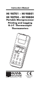
Instruction Manual HI 98701 - HI 98801 HI 98704 - HI 98804 Portable Microprocessor Printing and Logging K-J-T Thermocouple Thermometers w w w . h a n n a i n s t .
Dear Customer, Thank you for choosing a Hanna Instruments Product. Please read this instruction manual carefully before using the instrument. This manual will provide you with all the necessary information for the correct use of the instrument, as well as a precise idea of its versatility in a wide range of applications. If you need additional technical information, do not hesitate to e-mail us at tech@hannainst.com. These instruments are in compliance with directives.
PRELIMINARY EXAMINATION Remove the instrument from the packing material and examine it carefully to make sure that no damage has occurred during shipping. If there is any damage, notify your Dealer. Each thermometer is supplied complete with: • AA size Alkaline Batteries (4 pcs) • Instruction Manual • Paper rolls (5 pcs) • Rugged Carrying Case. Note: Save all packing material until you are sure that the instrument functions correctly.
The Battery Error Preventing System (BEPS) recognizes batteries levels as they become weaker. To prolong battery life, the backlight and printing features are disabled when the batteries are getting low; "LOBAT" indication is displayed on LCD to warn the user of this condition. However, the meter continues to measure correctly even when the low battery indication is displayed. The meter automatically switches itself off when the batteries are too weak to support proper function.
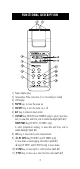
FUNCTIONAL DESCRIPTION 1) 2) 3) 4) 5) 6) 7) Power adapter plug Temperature Probe Connectors (1 or 4 according to model) LCD Display PAPER key, to move the paper up ON/OFF key, to turn the meter on or off ALT key, to alternate key function CH/TIME key (HI98704 and HI98804 only) to select input channels, to view date and time, and to enable backlight (with ALT) TEMP/TIME key (HI 98701, HI 98801 only) to select temperature reading, to view date and time, and to enable backlight (with ALT) 8) LOG key, to stor
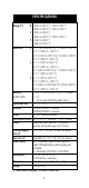
SPECIFICATIONS Range (*) K -200.0 to 999.9 °C ; 1000 to 1370 °C -300.0 to 999.9 °F ; 1000 to 2500 °F J -200.0 to 760.0 °C -300.0 to 999.9 °F ; 1000 to 1400 °F T -200.0 to 400.0 °C Resolution Accuracy (@20°C/68°F) -300.0 to 750.0 °F K 0.1°C (-99.9 to 999.9 °C); 1°C (1000 to 1370 °C) 0.2 °C (-200.0 to -100.0 °C) 0.2°F (-199.9 to 999.9 °F); 1°F (1000 to 2500°F) 0.3 °F (-300.0 to -200.0 °F) J 0.1 °C (-149.9 to 760.0 °C) 0.2 °C (-200.0 to -150.0 °C) 0.1 °F (32.0 to 999.9 °F); 1 °F (1000 to 1400 °F) 0.
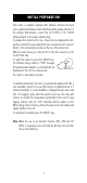
INITIAL PREPARATION Each meter is supplied complete with batteries. Remove the back cover, unwrap the batteries and install them while paying attention to the polarity. Alternatively, connect the HI 710005 or HI 710006 voltage adapter to the power adapter plug. To prepare the instrument for use, choose the most appropriate temperature probe(s) for your application (see accessories) and connect it (them) to the connector(s) located on the top of the instrument.
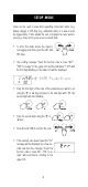
SETUP MODE Setup can be used to view data regarding instrument status (e.g. battery charge) or GLP data (e.g. calibration date) or to view or print the logged data. It also allows the user to change the meter parameters (e.g. time) and to gain access to stored data. • To enter this mode ensure the meter is not logging and then press the ALT and FNC keys.
PASSWORD PROTECTION Setting of the GLP parameters (calibration alarm time-out, instrument ID code, time and date) can be password protected. If password is set to a value different from 0000 (factory setting), the user will be asked to enter the password. • Select the desired GLP parameter code. • Enter the password by the arrow keys. • Press the ALT and CFM keys to confirm. • If password is wrong the meter will return to the function selection mode without any warning message.
Code Valid values Default 10 Show GLP data 11 Calibration alarm time-out On(enabled); Off(disabled) On 20 Instrument ID code 0000÷9999 0000 30 Current time3 hh:mm 00:00 31 Current day3 dd 01 32 Current month3 MM 01 33 Current year3 YYYY 1998 40 Auto-Off/Power down time-out Off,5,10,15,30,45,60 5 41 Battery level test 50 RS232 baud rate1 1200, 2400, 4800 4800 60 Firmware version 70 Thermocouple type selection "dEF"(K) ; "J"(J) ; "t"(T) "dEF" 71 Celsius/Fahrenheit selection °C ; °F °C 4 99 Password 0000÷9999
cod. 33: Year cod. 40: Auto OFF cod. 41: Battery test cod. 50: Baud rate cod. 60: Release code cod. 70: Thermocouple type cod. 71: Celsius or Fahrenheit cod. 99: Pass Code Some of the most important functions are explained below in a step by step sequence. TO SCAN LOGGED DATA (HI98801 and HI98804 only) COD. 00 - Lot data Printing / Scrolling • Select the code 00. • The message "Lot data Printing" will scroll twice across LCD. • The upper LCD will then display L 00 with the 00 blinking.
the last printed sample number. It is then possible to select another sample. • Press the ALT and FNC keys to return to setup mode. Viewing logged data • Press CH/TIME (HI98804 only) or TEMP/TIME (HI98801 only) to view data of the selected sample.
TO RESET PRINTING SAMPLE NUMBER (HI98701 and HI98704 only) This feature resets the print on demand sample number to 001. • Select the code 05 • A scrolling message will be displayed. • Press the ALT and CFM keys to confirm reset or ALT and FNC to escape. GLP DATA Cod. 10 - viewing GLP data • Select the code 10 • A message will scroll twice across LCD. • The LCD will then display the instrument identification (ID) code.
TAKING TEMPERATURE MEASUREMENTS To prepare the instrument for use, choose the most appropriate temperature probe(s) for your application (see accessories) and connect it (them) to the connector(s) located on the top of the instrument. The factory default thermocouple type is K, represented with the "dF" indication. If needed, select a different type (J and T types also available) through setup code 70. With the meter facing you, channel #1 is the first connector on the top left hand side.
TEMPERATURE CALIBRATION PROCEDURES (for technical personnel only) The meter is factory calibrated. However, as a general rule, it is recommended to have all thermometers recalibrated at least once a year. It is recommended that recalibration is performed by authorized technical personnel only to assure the accuracy of the instrument. Contact your nearest HANNA service center for a quick and accurate annual recalibration. Both thermocouple inputs and cold junction can be calibrated.
THERMOCOUPLE CALIBRATION 1. With a mV simulator, input 0.000 mV at channel #1 of the meter. 2. Ensure the meter is not displaying the cold junction temperature and press ALT, CFM and PAPER simultaneously while the meter is not printing nor logging to enter calibration mode. 3. User is prompted to enter password if it has been set to a value different from 0000, otherwise skip to step 6. 4. Enter the password using the arrow keys. 5. Press ALT and CFM to confirm or CH/TIME or TEMP/TIME to exit. 6.
HI 98801 - HI 98804 PRINTING / LOGGING FUNCTIONS Two different modes to print / log data are available: 1. Timed logging; samples are stored and printed (if print function is active) at fixed time intervals. Data are stored in the lots 01 to 16. 2. Log on demand; samples are stored and printed (if print function is active) when the LOG key is pressed. Data are stored in the lot 00. It's possible to perform the Log on demand either in normal mode or in Timed logging mode.
logged reading will appear briefly on the LCD. To reactivate the LCD press ON/OFF. TO STOP LOGGING In order to stop the recording mode, press ALT and LOG keys (press ON/OFF first, if meter is in sleep mode). A last printout reporting the number of logged samples (e.g. S.00009) will be produced if printer is enabled. Notes: • It is recommended to use the adapter during logging in printing mode, especially when many printouts are going to be taken.
the value will be stored in the lot 00 (log on demand data area). If the print function is enabled, a printout is also produced providing the following information: a - Date b - Sample number c - Time d - Readings ("----" means out of range or probe not connected) Note: When the Log on demand data area is full and the LOG key is pressed, the sample will not be stored and the LCD will display "FULL". In this case it is necessary to delete the Log on demand data to proceed.
TO RETRIEVE LOGGED DATA Logged data can be viewed on LCD or printed. To view or print logged data see "TO SCAN LOGGED DATA" in the "SETUP MODE" paragraph. The logging meters also allow the downloading of logged data to PC. To download data to PC see "DATA TRANSFER TO PC" paragraph. HI 98701 - HI 98704 PRINTING FUNCTIONS Two different modes to print data are available: 1. Timed printing; samples are printed at fixed time intervals. Data lots from 01 to 16 are available. 2.
TO STOP PRINTING In order to stop the recording mode, press ALT and LOG keys (press ON/OFF first, if meter is in sleep mode). A last printout reporting the number of printed samples (e.g. S.00009) will be produced. Notes: • It is recommended to use the adapter during printing mode, especially when many printouts are going to be taken. • Before proceeding with printing, make sure there is enough paper for your measurements.
GOOD LABORATORY PRACTICE (GLP) GLP is a set of functions that allows the storage or retrieval (when necessary) of data regarding the maintenance and status of the meter. LAST CALIBRATION DATE Last calibration date is stored automatically after a successful calibration. The last calibration date can be displayed through setup code 10 (see "SETUP MODE" paragraph). CALIBRATION ALARM TIME-OUT The meter checks if the time-out time, fixed at 1 year, has expired every time it is turned on.
DATA TRANSFER TO PC HI 98801 - HI 98804 only HI98801 and HI98804 contain infrared transmitting circuitry. Ensure there isn't any logging process active. Press CH/TIME or TEMP/TIME to set the meter to time or date mode and simply place your data-logger on a HI9200 Infrared Transmitter (ensuring that the two infrared LEDs are placed on top of each other) and the memory content can then be downloaded to your PC through the HI9200's RS232 port.
MEMORY ORGANIZATION HI 98801 - HI 98804 only Logged data are stored in the internal EEPROM and are retained even if batteries and external power are disconnected. MEMORY CAPACITY • 14000 data samples divided into 16 lots (lots 01 to 16) • 9999 data samples maximum for a single channel • 300 data samples for the Log on demand (lot 00). TIMED LOG (lots 01 to 16) Each time a new logging period starts, it automatically starts from the next available lot.
PRINTER MAINTENANCE TO CHANGE THE INK CARTRIDGE When printouts become faint, it might be necessary to change the ink cartridge. Contact your Hanna authorized center. TO INSERT THE PAPER ROLL The meters use plain paper rolls 38 mm width. To insert a new roll open the paper cover pulling it gently and take the cylinder away. Insert the paper edge in the printer slot and feed the printer by pressing the PAPER key. Allow about 5 cm (2") of paper to exit from the printer and replace the paper cover.
BATTERY REPLACEMENT When the batteries are inserted and no power adapter is connected, the meter can recognize different batteries charge levels. 1. Fully charged batteries. The backlight and printer can be enabled. 2. Weakening batteries - "LOBAT" symbol blinks on LCD. The backlight and printer are automatically disabled and it is not possible to enable them until new batteries are inserted or an external power adapter is connected. 3. Weak batteries - "LOBAT" symbol stays still on lower LCD.
K-TYPE THERMOCOUPLE PROBES WITH DETACHABLE HANDLE & MINI-CONNECTOR (to be plugged into HI 766HD probe handle) HI 766PA Roller surface probe, max 320°C/600°F 100mm 4" 280mm 7.8" 11" HI 766PB Surface probe, max 650°C/1200°F 200mm 7.9" HI 766PC Penetration probe, max 900°C/1650°F 155mm 6.1" 3mm 0.12" HI 766PD Air probe, max 300°C/570°F 3mm 0.12" 250mm 9.
HI 766PE1 General use probe, max 900°C/1650°F 155mm 6.1" 3mm 0.12" HI 766PE2 General use probe, max 900°C/1650°F 200mm 7.8" 5mm 0.20" HI 766HD Rugged thermocouple probe handle with 1m (3.3' ) cable fitted with a mini-connector WITH INTEGRAL HANDLE, 1 m CABLE & MINI-CONNECTOR HI 766A Roller surface probe, max 320°C/600°F 100mm 4" 280mm 11" 420mm 13.3" 16.5" HI 766B Surface probe, max 650°C/1200°F 400mm 15.7" 260mm 10.
HI 766B1 90° surface probe, max 450°C/840°F 30mm 1.2" 300mm 11.8" HI 766B2 Surface probe, max 900°C/1650°F 8mm 0.3" 130mm 5.1" HI 766B3 Small surface probe with insulated shaft, max 200°C/390°F 5mm 0.2" 130mm 5.1" HI 766C Penetration probe, max 900°C/1650°F 260mm 10.3" 120mm 4.8" 3mm 0.12" HI 766D Air probe, max 300°C/570°F 385mm 15.2" 245mm 9.6" 3mm 0.12" HI 766E1 General use probe, max 900°C/1650°F 260mm 10.2" 120mm 4.7" 29 3mm 0.
HI 766E2 General use probe, max 900°C/1650°F 360mm 13.8" 220mm 8.5" 5mm 0.2" HI 766F High temperature wire probe without handle, max 1100°C/2000°F 255mm 10" 1.5mm 0.06" HI 766F1 Flexible probe without handle, max 480°C/900°F 2mm 0.08" 1m 3.3’ HI 766TV1 Pipe clamp probe, max 200°C/390°F 35mm Max. 1.
WARRANTY All Hanna Instruments meters are warranted for two years against defects in workmanship and materials when used for their intended purpose and maintained according to instructions. The electrodes and the probes are warranted for a period of six months. This warranty is limited to repair or replacement free of charge. Damages due to accident, misuse, tampering or lack of prescribed maintenance are not covered. If service is required, contact the dealer from whom you purchased the instrument.
MAN98804R2 03/02 w w w . h a n n a i n s t .