Instruction Manual HI 9914 Wall mounted Fertigation Controller Manufacturers since 1978 1 These Instruments are in Compliance with the CE Directives
Dear Customer, Thank you for choosing a Hanna Product. Please read this instruction manual carefully before using the instrument. This manual will provide you with the necessary information for a correct use of the instrument, as well as a precise idea of its versatility. If you need more technical information, do not hesitate to e-mail us at tech@hannainst.com. These instruments are in compliance with CE directives. TABLE OF CONTENTS PRELIMINARY EXAMINATION ................................................
PRELIMINARY EXAMINATION Remove the instrument from the packing material and examine it carefully to make sure that no damage has occurred during shipping. If there is any noticeable damage, notify your Dealer. Note: Save all packing materials until you are sure that the instrument functions correctly. Any defective item must be returned in the original packaging, together with the supplied accessories. • Read carefully the instructions before using the instrument.
tivity of the irrigation water, while the pH regulator can be set for high or low pH correction. For a better result, the Conductivity and pH controls are time separated and a timed operation mode avoids overdosing of fertilizer or acid. The controller is designed with relay outputs for pH and Conductivity control (2A/240V), each one corresponding to a status LED for visual check. Three level sensors are used to offer the best control of water level, alarm conditions and irrigation sequences.
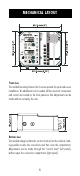
MECHANICAL LAYOUT Front view The molded mounting holes in the 4 corners provide for quick and secure installation. No additional tool is needed. All the electrical connections and control are located on the front panels so that adjustments can be made without removing the unit. Bottom view The modular design isolates the control circuitry from the contacts, making possible to wire the connections and then close the compartment.
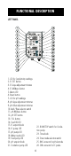
FUNCTIONAL DESCRIPTION LEFT PANEL 1. LCD for Conductivity readings 2. EC SET button 3. EC slope adjustment trimmer 4. EC MEAsure button 5. Alarm LED 6. Reset button 7. LCD for pH readings 8. pH slope adjustment trimmer 9. pH offset adjustment trimmer 10. Acid / Base selector switch 11. pH MEAsure button 12. pH SET button 13. FILL button 14. Feed OK LED 15. EC setpoint knob 16. EC pump LED 17. pH pump LED 18. Water nozzle LED 19. Feed pump LED 20. pH setpoint knob 21. Circulation pump LED 22.
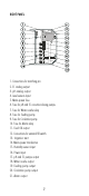
RIGHT PANEL 1. Connections for matching pin 2. EC analog output 3. pH analog output 4. Level sensors input 5. Mains power fuse 6. Fuse for pH and EC correction dosing pumps 7. Fuse for Water nozzle relay 8. Fuse for Feeding pump 9. Fuse for Circulation pump 10. Fuse for Alarm relay 11. Feed OK output 12. Connections for external fill switch 13. Irrigation start 14. Mains power transformer 15. Humidity sensor input 16. Power input 17. pH and EC pumps output 18. Water nozzle output 19.
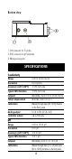
Bottom view 1. DIN connector for EC probe 2. BNC connector for pH electrode 3. Wiring access ports SPECIFICATIONS Conductivity Range Resolution Accuracy (@20ºC/68ºF) Typical EMC deviation Setpoint Temp.Compensation Calibration Analog output Controller output pH Range Resolution Accuracy (@20ºC/68ºF) Typical EMC deviation Setpoint Calibration 0.00 to 10.00 mS/cm 0.01 mS/cm ±5% Full Scale ±2% Full Scale Adjustable, from 0.50 to 10.
Analog output Controller Output other features Timer Feed OK output Humidity sensor Water nozzle output Circulation pump output Feeding pump output Alarm output Water level inputs User input External FILL button Power supply Environment Dimensions Weight 0-7V ±5% (0.
INSTALLATION Install the HI 9914 controller on a wall, indoors, in a dry area and not under direct sun light. Assure that liquids can not be sprayed or poured on it. Fix the controller at a proper height to easily reach the front panels and fix the 4 screws at the 4 corners. Install the controller near the tank to keep short the cables of pH electrode and Conductivity probe. Assure the proper working voltage.
Typical arrangements for the Tank assembly Complete tank assembly: all the sensors and pumps are mounted; the best control of water composition and irrigation sequence is assured. The inlet and outlet of the circulation pump are below the Low Level to avoid that the pH electrode remains dry. Simplified tank assembly: the low level detector is not used; the controller does not react if the water level is too low.
Minimal tank assembly: only the normal level sensor is used, the irrigation is made manually, regardless of the water composition or level. The controller will refill the tank if the water goes under normal level for about 15 minutes or if the fill button is pressed. Note: The inlet of the circulation pump must be below its outlet to avoid damages to the pump itself. CONNECTIONS AND WIRING Wiring the controller • Make sure the power supply is disconnected.
• If the matching pin is used, connect the matching pin terminal to the connector pin 2 located on the right panel. • Immerse the matching pin near the pH electrode. Conductivity probe connection • Attach the conductivity probe (HI7632/D or HI3003/D) to the DIN socket located on the bottom of the controller. Align the guide on the connector with the socket, push-in the connector and tighten the retainer ring.
• Place the low-level sensor to indicate the minimum water level for the correct function of both the circulation and feeding pumps. • Connect the sensor between INPUT COMMON and LOW LEVEL pins. • Place the normal-level sensor to indicate the filling level when the tank is full. • Connect the sensor between INPUT COMMON and NORMAL LEVEL pins. • Place the alarm-level sensor to limit the highest water level. • Connect the sensor between INPUT COMMON and HIGH (ALARM) LEVEL pins.
External fill button connection • Connect the button between FILL and INPUT COMMON pins. • The tank will be immediately filled with water if the external fill button is pressed and the water level is below the normal level float. External FEED OK connection This output is a current source from the FEED OK pin. • Connect a LED, buzzer or other device between FEED OK and INPUT COMMON pins. • When the water composition is good for irrigation, the FEED OK will source about 15mA and activate the device.
pin is the same, so that the voltage of the power source has to match the working voltage of the selected device and both the pH and EC correction pumps have to work at the same voltage. Acid and fertilizer dosing pump connection The pH and EC correction relays (2A, 240V) have a common pin: if the pH correction pump is on, the COMMON pin is connected to the pH PUMP pin; if the EC pump is activated, the COMMON pin is connected to the FERT. PUMP pin. • Connect one pin of the source to the COMMON pin.
Water nozzle, Circulation and Feeding pump connection The Water nozzle, Circulation pump and Feeding pump outputs are relay type (2A, 240V). Both the NO (normally open) and NC (normally closed) contacts are available to the user. If the device is off, the COMMON pin is connected to corresponding NC pin. If the device is on, the COMMON pin is connected to the NO pin. • Connect one pin of the source to the COMMON pin. • Connect the device between the NO pin and the remaining source pin.
Main power supply connection Before connecting the unit to the mains, make sure the controller is completely wired and all the connections for pumps, alarm, probes, etc. have been done. • Connect the mains power wires to the power supply input pins. • Replace the right panel lid and tighten the four provided screws. • Connect the controller to the mains.
- When the water is good for irrigation, the Feed OK LED is ON. - If any alarm condition occurs (see pag.22), the ALARM LED turns ON. The controller can be restarted by pressing the RESET button. If the alarm condition is still present, the controller goes back in alarm status. When the controller is powered, the actual pH and conductivity values are displayed on the two LCDs in pH and mS/cm units respectively.
Step 4: The water nozzle is closed, circulation pump is running and the Conductivity & pH controls are activated. The Conductivity control has the priority over the pH control. • If the timer feature is activated, the control is on for a selected period (1-10 minutes) and off for the remaining period until 15 minutes. • If both the conductivity and pH values are good for at least 30 seconds, the controller goes to step 5.
If the CONT/PAUSE switch of the Circulation pump is in CONT position, the circulation pump will act as described above. If the CONT/PAUSE switch of the Circulation pump is in PAUSE position, the circulation pump will not run the step 5. When the low-level sensor is not used, the low-level condition is not sensed by the controller. The user must take care to stop the user input command before the water in the tank goes below the low level.
ALARM CONDITIONS When an alarm condition is reached, the ALARM LED turns ON and the alarm relay contact is closed (short between the COMMON and NO pins). All the pumps and the water nozzle are off. The Conductivity and pH measuring channels display the EC and pH values.
CONTROLLER SETTINGS SETTING THE pH CONTROL To adjust the pH setpoint: • Press the SET button close to the pH display to read the setpoint value. • Turn the SET knob until the display shows the desired value. • Return to measurement mode by pressing the MEA button. To select the dosing direction: • Select the desired solution for pH correction by setting the ACID/BASE switch. • If the switch is in the ACID position, the pH pump is activated when the pH value exceeds the setpoint.
• Turn the SET knob until the display shows the desired value. •Turn back in measurement mode by pressing the MEA button. Note: The internal pH and EC regulators have a small hysteresis to prevent oscillations of the relay output that can damage the pumps. As a result, the selected pH and EC values are equal to the set value ± hysteresis value. SETTING EC AND pH CONTROL TIMERS The Timer feature is provided to avoid overdosing in a system with a long response time.
SETTING THE CIRCULATION PUMP WORKING REGIME • Set the CONT/PAUSE switch to CONT to enable a continuous running of the Circulation pump (if no ALARM condition is present). • Set the CONT/PAUSE switch to PAUSE to stop the Circulation pump after the good water composition is reached (do not run the Step 5). The pump will start again when an adjustment of water composition is needed or the irrigation takes place.
CALIBRATION Disconnect the pumps, the water nozzle and the alarm or assure that the start of one of them will cause no damage. ON, OFF or blinking LEDs have no effect on the measurement and calibration of pH and EC. pH CALIBRATION To calibrate the controller, first set it in measurement mode by pressing the MEA button (MEA LED is on). Make sure the pH electrode and matching pin have been properly connected and wired to the controller, and the meter is plugged to the mains.
Slope adjustment • Rinse the electrode and the ground probe thoroughly with water and immerse the bottom 4 cm (1.5") in a pH10.01 (HI 7010) or a pH4.01 (HI 7004) buffer solution. • Stir the electrode and wait for the reading to stabilize before adjusting the SLOPE trimmer to display the correct pH value at the measured solution temperature; e.g. 4.01 (or 10.01) at 25°C (77°F). See the “pH VALUES AT DIFFERENT TEMPERATURES” section. The pH calibration is now complete.
• Stir the probe and tap it gently to the bottom of the beaker to ensure that any air bubbles trapped inside it. For best results, do not put the probe close to the walls of the beaker or lying on the bottom. • Wait for the reading to stabilize. Adjust the SLOPE trimmer to display the same value as the calibration solution @25°C. For example, with HI 7039 buffer solution, adjust the trimmer to display “5.00”.
pH ELECTRODE CONDITIONING & MAINTENANCE Preparation Remove the protective cap. DO NOT BE ALARMED IF ANY SALT DEPOSITS ARE PRESENT. This is normal with pH electrodes and they will disappear when rinsed with water. During transportation tiny air bubbles may have formed inside the glass bulb (membrane). Shake down the electrode, as you would do with a glass thermometer to remove the bubbles. If the bulb and/or junction are dry, soak the electrode overnight in HI 70300 Storage Solution.
Troubleshooting Evaluate the electrode performance based on the following: • Noise (readings fluctuate up and down) could be due to clogged/dirty junction: - Dry Membrane/Junction: soak in HI 70300 Storage Solution overnight. Check that the installation has been done to create a well to maintain the electrode bulb constantly moist. • Low Slope: - Check the electrode for cracks in the glass stem or bulb (replace the electrode if cracks are found).
CONDUCTIVITY PROBE MAINTENANCE Preparation Make sure that the protective sleeve is on the probe shaft and is intact. Storage Conductivity probes should be stored dry. If they are not to be used for a while, clean and dry them thoroughly before storing them in a dry place. Periodic maintenance Inspect the probe and the cable. The cable used for the connection to the controller must be intact. There must be no points of broken insulation on the cable or cracks on the probe sleeve.
- Air bubbles also disturb measurements and the probe should be installed in such a way as to minimize them. Note: It is always recommended to keep at least one spare probe handy. When anomalies are not resolved with a simple maintenance, change the electrode (and recalibrate the controller) to see if the problem is alleviated. Note: Ensure that the probe is installed in such a way that it permanently lies in the solution whether in the tank or the circulation pipe.
APPENDIX - A pH VALUES AT VARIOUS TEMPERATURES. The temperature directly affects the pH value. For example, if the buffer’s temperature is 25°C (77°F), calibrate the meter to read 7.01, 4.01 or 10.01; if the temperature is 20°C, calibrate the meter to 7.03, 4.00 or 10.06; if the temperature is 50°C, calibrate the meter to 6.98, 4.06 or 9.82; etc. Please refer to the following chart for a more accurate pH calibration.
APPENDIX - B Composition of nutrient solution for several plants growth in hydroponic system utilized in nursery and cutting plants cultivation.
Reference: “Principi tecnico-agronomici della fertirrigazione e del fuori suolo”, pag.115, published by “Veneto Agricoltura-Centro Sperimentale Ortofloricolo Po di Tramontana”, coordinator Prof. F.Pimpini, Agricultural Faculty, University of Padova - Oct.
APPENDIX - C INSTALLATION EXAMPLES Block diagram for a typical installation of an irrigation system, with HI9914 controller.
Block diagram for an irrigation system with recirculation circuit.
WARRANTY All Hanna controllers are warranted for two years against defects in workmanship and materials when used for their intended purpose and maintained according to instructions. Electrodes and probes are warranted for a period of six months. Damages due to accident, misuse, tampering or lack of prescribed maintenance are not covered. This warranty is limited to free of charge or replacement of the meter only, if any malfunctioning is due to manufacturing defects.
CE DECLARATION OF CONFORMITY Recommendations for Users: Before using this product, make sure that it is entirely suitable for the environment in which it is used. Operation of this instrument in residential area could cause unacceptable interferences to radio and TV equipment. Any variation introduced by the user to the supplied equipment may degrade the instrument’s EMC performance. Unplug the instrument from the power supply before replacing the fuse or making any electrical connections.
MAN9914 07/02 w w w . h a n n a i n s t .