Instruction Manual HI 9914 Wall mounted Fertigation Controller w w w . h a n n a i n s t .
Dear Customer, Thank you for choosing a Hanna Product. Please read this instruction manual carefully before using the instrument. This manual will provide you with the necessary information for a correct use of the instrument, as well as a precise idea of its versatility. If you need more technical information, do not hesitate to e-mail us at tech@hannainst.com. This instrument is in compliance with CE directives. TABLE OF CONTENTS PRELIMINARY EXAMINATION ...................................................
tivity of the irrigation water, while the pH regulator can be set for high or low pH correction. For a better result, the conductivity and pH controls are time separated and a timed operation mode avoids overdosing of fertilizer or acid. The controller is designed with relay outputs for pH and conductivity control (2A/240V), each one corresponding to a status LED for visual check. Three level sensors are used to offer the best control of water level, alarm conditions and irrigation sequences.
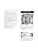
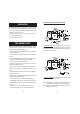
FUNCTIONAL DESCRIPTION RIGHT PANEL LEFT PANEL 1. LCD for Conductivity readings 2. EC SET button 3. EC slope adjustment trimmer 4. EC MEAsure button 5. Alarm LED 6. Reset button 7. LCD for pH readings 8. pH slope adjustment trimmer 9. pH offset adjustment trimmer 10. Acid / Base selector switch 11. pH MEAsure button 12. pH SET button 13. FILL button 14. Feed OK LED 15. EC setpoint knob 16. EC pump LED 17. pH pump LED 18. Water nozzle LED 19. Feed pump LED 20. pH setpoint knob 21. Circulation pump LED 22.
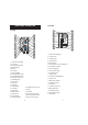
Bottom view Analog output Controller Output Other Features Timer 1. DIN connector for EC probe 2. BNC connector for pH electrode 3. Wiring access ports SPECIFICATIONS Conductivity Range Resolution Accuracy (@20ºC/68ºF) Typical EMC Deviation Setpoint Temp.Compensation Calibration Analog output Controller output pH Range Resolution Accuracy (@20ºC/68ºF) Typical EMC deviation Setpoint Calibration 0.00 to 10.00 mS/cm 0.01 mS/cm ±5% Full Scale ±2% Full Scale Adjustable, from 0.50 to 10.
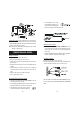
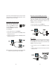
INSTALLATION Typical arrangements for the Tank assembly Install the HI 9914 controller on a wall, indoors, in a dry area and not under direct sun light. Assure that liquids can not be sprayed or poured on it. Fix the controller at a proper height to easily reach the front panels and fix the 4 screws at the 4 corners. Install the controller near the tank to keep short the cables of pH electrode and Conductivity probe. Assure the proper working voltage.
• If the matching pin is used, connect the matching pin terminal to the connector pin 2 located on the right panel. • Immerse the matching pin near the pH electrode. Minimal tank assembly: only the normal level sensor is used, the irrigation is made manually, regardless of the water composition or level. The controller will refill the tank if the water goes under normal level for about 15 minutes or if the fill button is pressed.
• Place the low-level sensor to indicate the minimum water level for the correct function of both the circulation and feeding pumps. • Connect the sensor between INPUT COMMON and LOW LEVEL pins. • Place the normal-level sensor to indicate the filling level when the tank is full. • Connect the sensor between INPUT COMMON and NORMAL LEVEL pins. • Place the alarm-level sensor to limit the highest water level. • Connect the sensor between INPUT COMMON and HIGH (ALARM) LEVEL pins.
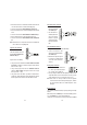
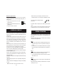
pin is the same, so that the voltage of the power source has to match the working voltage of the selected device and both the pH and EC correction pumps have to work at the same voltage. Acid and fertilizer dosing pump connection The pH and EC correction relays (2A, 240V) have a common pin: if the pH correction pump is on, the COMMON pin is connected to the pH PUMP pin; if the EC pump is activated, the COMMON pin is connected to the FERT. PUMP pin.
Main power supply connection Before connecting the unit to the mains, make sure the controller is completely wired and all the connections for pumps, alarm, probes, etc. have been done. • Connect the mains power wires to the power supply input pins. • Replace the right panel lid and tighten the four provided screws. • Connect the controller to the mains.
Step 4: The water nozzle is closed, circulation pump is running and the Conductivity & pH controls are activated. The Conductivity control has the priority over the pH control. • If the timer feature is activated, the control is on for a selected period (1-10 minutes) and off for the remaining period until 15 minutes. • If both the conductivity and pH values are good for at least 30 seconds, the controller goes to step 5.
ALARM CONDITIONS When an alarm condition is reached, the ALARM LED turns ON and the alarm relay contact is closed (short between the COMMON and NO pins). All the pumps and the water nozzle are off. The Conductivity and pH measuring channels display the EC and pH values.
• Turn the SET knob until the display shows the desired value. •Turn back in measurement mode by pressing the MEA button. SETTING THE CIRCULATION PUMP WORKING REGIME Note: The internal pH and EC regulators have a small hysteresis to prevent oscillations of the relay output that can damage the pumps. As a result, the selected pH and EC values are equal to the set value ± hysteresis value.
CALIBRATION Disconnect the pumps, the water nozzle and the alarm or assure that the start of one of them will cause no damage. ON, OFF or blinking LEDs have no effect on the measurement and calibration of pH and EC. pH CALIBRATION To calibrate the controller, first set it in measurement mode by pressing the MEA button (MEA LED is on). Slope adjustment • Rinse the electrode and the ground probe thoroughly with water and immerse the bottom 4 cm (1.5") in a pH10.01 (HI 7010) or a pH4.
• Stir the probe and tap it gently to the bottom of the beaker to ensure that any air bubbles trapped inside it. For best results, do not put the probe close to the walls of the beaker or lying on the bottom. • Wait for the reading to stabilize. Adjust the SLOPE trimmer to display the same value as the calibration solution @25°C. For example, with HI 7039 buffer solution, adjust the trimmer to display “5.00”.
Troubleshooting Evaluate the electrode performance based on the following: • Noise (readings fluctuate up and down) could be due to clogged/dirty junction: - Dry Membrane/Junction: soak in HI 70300 Storage Solution overnight. Check that the installation has been done to create a well to maintain the electrode bulb constantly moist. • Low Slope: - Check the electrode for cracks in the glass stem or bulb (replace the electrode if cracks are found).
- Air bubbles also disturb measurements and the probe should be installed in such a way as to minimize them. Note: It is always recommended to keep at least one spare probe handy. When anomalies are not resolved with a simple maintenance, change the electrode (and recalibrate the controller) to see if the problem is alleviated. Note: Ensure that the probe is installed in such a way that it permanently lies in the solution whether in the tank or the circulation pipe.
APPENDIX - B Composition of nutrient solution for several plants growth in hydroponic system utilized in nursery and cutting plants cultivation. Reference: “Principi tecnico-agronomici della fertirrigazione e del fuori suolo”, pag.115, published by “Veneto Agricoltura-Centro Sperimentale Ortofloricolo Po di Tramontana”, coordinator Prof. F.Pimpini, Agricultural Faculty, University of Padova - Oct.
APPENDIX - C INSTALLATION EXAMPLES Block diagram for a typical installation of an irrigation system, with HI9914 controller. 36 Block diagram for an irrigation system with recirculation circuit.
WARRANTY CE DECLARATION OF CONFORMITY All Hanna controllers are warranted for two years against defects in workmanship and materials when used for their intended purpose and maintained according to instructions. Electrodes and probes are warranted for a period of six months. Damages due to accident, misuse, tampering or lack of prescribed maintenance are not covered. This warranty is limited to free of charge or replacement of the meter only, if any malfunctioning is due to manufacturing defects.
SALES AND TECHNICAL SERVICE CONTACTS Australia: Tel. (03) 9769.0666 • Fax (03) 9769.0699 China: Tel. (10) 88570068 • Fax (10) 88570060 Egypt: Tel. & Fax (02) 2758.683 Germany: Tel. (07851) 9129-0 • Fax (07851) 9129-99 Greece: Tel. (210) 823.5192 • Fax (210) 884.0210 Indonesia: Tel. (21) 4584.2941 • Fax (21) 4584.2942 Japan: Tel. (03) 3258.9565 • Fax (03) 3258.9567 Korea: Tel. (02) 2278.5147 • Fax (02) 2264.1729 Malaysia: Tel. (603) 5638.9940 • Fax (603) 5638.9829 Singapore: Tel. 6296.