Hanover Outdoor Furniture IMPORTANT If you have any problems with this product (missing or damaged parts, assembly issues, etc.), PLEASE DO NOT RETURN TO THE RETAILER/STORE from where you purchased the product. Please call our Toll‐Free Customer Service Hotline at: 1‐800‐416‐3511 Between 9:00 AM and 5:00 PM Eastern Time, Monday through Friday Or visit our website at: www.hanover‐products.
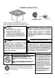
ASSEMBLY INSTRUCTIONS CSA Model 99000 ARL00100 Installer: Leave these instructions with consumer. Consumer: Keep these instructions for future reference. DANGER If you smell gas: 1. Shut off gas to the appliance. 2. Extinguish any open flame. 3. If odor continues, keep away from the appliance and immediately call your gas supplier or fire department. WARNING: Improper installation, adjustment alteration, service or maintenance can cause injury or property damage.
IMPORTANT SAFETY INFORMATION The installation must conform with local codes or, in the absence of local codes, with the National Fuel Gas Code, ANSI Z223.1/NFPA 54; International Fuel Gas Code. ; Natural Gas and Propane Installation Code, CSA B149.1; or Propane Storage and Handling Code, B149.2, as applicable.
IMPORTANT SAFETY INFORMATION ABOUT PROPANE (LP) GAS A self contained LP-gas cylinder for use with this appliance must have a capacity of 20 lbs. and must be equipped with a Type 1 connector and an OPD (overfill protection device). See Figure 1. The LP-gas supply cylinder to be used must be constructed and marked in accordance with the specification for LP-gas cylinders of the U.S.
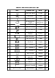
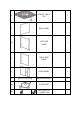
PARTS IDENTIFICATION LIST PART DESCRIPTION PART# QTY A CONTROL KNOB FP1245 1 B GAS VALVE FP0307 1 C THERMOCOUPLE FP0004 1 D LP REGULATOR HOSE 65-FP-0181 1 E ELECTRODE 65-FP-0128 1 F ORIFICE ELBOW FP0310 1 G IGNITION MODULE FP0006 1 ZCF0021 1 HW0705 1 H I PROPANE ORIFICE “AAA” BATTERY(1.
U FIREPIT TABLE TOP 1 V BACK PANEL 1 W LEFT SIDE PANEL 1 X RIGHT SIDE PANEL 1 Y DOOR PANEL 1 Z MIDDLE SUPPORT 1 AA LP SUPPORT 1 BB BOTTOM/ TOP CONNECTOR 1
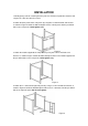
INSTALLATION 1.Identify parts packed in carton against the parts list. Remove all protective materials and set parts on a flat, non-abrasive surface. 2. Attach the back panel to the side panels by using four 1/4"x40 mm bolts and washers as shown in Figure 2.Guide the bolts through the holes in back panel, into the pre-drilled holes in the side panels. Hand tighten only. Figure 2 3. Attach the middle support to the side panels by using four 1/4"x15 mm bolts and washers as shown in Figure 3.
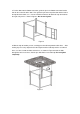
5. Put the door onto the bottom connector, guide the pin in the bottom connector into the hole on the underside of the door. Then guide the pin on the top connector into the hole in the topside of the door, use a 1/4"x15 mm bolt and washer to attach this top connector to the right side panel as shown in Figure 5. Do not over tighten. Figure 5 6. With the help of another person, carefully place the table top onto the table base.
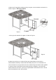
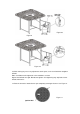
7. Attach the LP support the to door panel by using four 1/4"x15 mm bolts and washers as shown in Figure 7. Do not over tighten. Figure 7 8. Place gas tank onto the LP support as shown in Figure 8. Figure 8 9. Attach the metal ring ( as shown in Figure 9) pre-fitted with gas hose which is connected to the table top , into the hole of the door panel, then use hex bolt driver to screw 1/4"x5mm nut , the gas tank has fixed as shown in Figure 9a. Connect the regulator as shown in Figure.
Figure 9a Figure 9 Figure 10 10. After making any necessary adjustments to the parts, use the hex bolt driver to tighten all bolts. Note: each bolt must be tightened a few revolutions at a time. Repeat until all bolts are tight. Do not over tighten. Over tightening may strip bolts. Cover all bolts with covers. 12. Pour the lava rocks into the burner pan completely covering the burner. See Figure 11.
13. Remove the cardboard cover from the ignition well as shown in Figure 12. Remove any lava rock or fire ice on top of ignition well. Cardboard Cover Figure 12 14. Open the tank valve. Apply a solution of soapy water to the tank-regulator connection and to the valve-hose connection to check for leaks as shown in Figure 13. If soap bubbles continue to form, the connection has a leak. If a leak is found, close the tank valve and tighten all connections. NOTE: NEVER USE A FLAME TO CHECK FOR LEAKS.
LIGHTING INSTRUCTIONS Warning: If these instructions are not followed exactly, a fire or explosion may result causing property damage, personal injury or loss of life. 1. Make sure the control knob is in the "OFF" position. See Figure 15 Open the tank valve all the way. IGNITER BUTTON Figure 15 CONTROL KNOB 2. Push in the igniter button. You will hear a slight clicking sound. With the igniter button pushed in, push and turn the control knob to the “ON” position.
TROUBLESHOOTING GUIDE PROBLEM CAUSE REMEDY No Propane Gas at Burner Check that gas tank valve is open. Turn control knob to “ON” and push control knob in. Make sure tank has propane gas. Burner won’t light No Spark at Electrode Burner won’t stay lit after lighting Check that AAA battery is installed with negative (-) end first and has a charge. Check that the wire is connected to the ignition module. Check that the electrode is not cracked or broken.
IMPORTANT!! PLEASE READ ENTIRE INSTRUCTION SHEET BEFORE ASSEMBLY!! TO EXPEDITE ANY FUTURE WARRANTY CLAIMS, PLEASE KEEP INSTRUCTION SHEET, WARRANTY CARD AND RECEIPT Fig.1 Step 1: Identify all parts packed in carton against the parts list. Remove all protective materials. Place parts on a non-abrasive surface to avoid scratching. I f you are missing any parts or are unsure how to proceed with the assembly, call our Customer Service Center at 1-800-416-3511.