
Use and Care Guide


Page 4
ASSEMBLY INSTRUCTIONS
1
2
3
Place the table top upside down on a flat, non-abrasive surface. Attach table leg to table top by using a 1/4"x20 mm
bolt and a washer as shown in .
Repeat for the other three legs.
Attach the topside support to the table top by using two 1/4"x20 mm bolts and washers as shown in .
Repeat for the opposite side.
Fig 1
Hand tighten only.
Fig 1 Hand
tighten only.
.
.
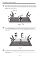
Place the leg beneath the table rim corner bracket. Guide the bolt through the
hole in the table rim and into the pre-drilled hole in the table leg.
Attach a leg to the leg connector bracket by carefully guiding the bolts already in place on the table legs (each leg
has two bolts) through the holes in the leg connector bracket. Add a washer and a nut to the end of each bolt as
shown in . Repeat on the other three legs.Fig. 2 Hand tighten only. Attach topside support to leg connector
bracket by using a 1/4"x30 mm bolt and a washer as shown in . Repeat for the other
topside support.
Fig. 2 Hand tighten only.
L
G
H
H
F
K
B
Fig.2
After making any necessary adjustments to the alignment of the table legs and the leg connector bracket, use the
hex bolt driver and hex wrench to tighten all nuts and bolts. each bolt and nut must be tightened a few
revolutions at a time. In order to apply equal pressure to all bolt joints, we recommend working in a cross corner
(X fashion). Repeat until all bolts are tight. . Over tightening may strip bolts. Cover all nuts
and bolts with covers.
Note:
Do not over tighten
K
E
H
C
FOOT CAP
D
A
K
E
H
Fig.1