EXPEDI T OR Op e r a t i o n s Ma n u a l 1 SUN TELECOM INTL.
- Table of Contents - 1. What is Expeditor? 2. Expeditor Components 3. How to install Expeditor 4. Specifications 5. How to use The Expeditor 6. Troubleshooting 7. How to set up delay timing for Table Unit 8. Table Unit Delay timer set up 9. How to set up Chef Unit addresses 10. Warnings 2 SUN TELECOM INTL.
1. What is The EXPEDITOR? EXPEDITOR is a system designed to transfer data within a limited area such as a restaurant. This unique system increases the servers ability to service customers. This is done through increasing the efficiency of the server. 2 . EXPEDITOR Components. 1. Main Unit – Unit Body -1 ea, Antenna-2 ea, Bracket-4 ea, Screw (small) for Bracket-8 ea (3*8mm) Screw (Big) for fix-4 ea (4*20mm), Foot (rubber) for Housing-4 ea (20*20*3mm) 2.
bottom of unit body. 4. Server Unit 1) Install Server Unit batteries located on the back side of the unit. The Server Unit can be worn in the server band or can be worn in a holster. The server band is an elastic wrist watch type band that allows the server easy access to the Server Unit especially when the servers hands are full. The holster allows the Server Unit to be clipped to a piece of clothing. 4 . Specifications 1.
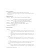
. How to use Expeditor 1. Main Unit 1) Plug the 9V/1.5A adaptor into any 110v wall outlet. Once the unit is plugged into the power supply, the red LED 9V Indicator will light. 2) Turn the power switch to ON. This switch is located on the bottom of the Main Unit body. This will cause the red LED 5V Indicator to be lit. 3) When data is sent from the Table Unit a GREEN data LED will blink.
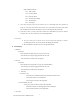
No. 1 : Ready to Order No. 2 : Need more Drinks No. 3 : Need more Bread No. 4 : Need Silverware/ Napkin No. 5 : Need Assistance No. 6 : Check please 3) Once a data selection is chosen by the customer, the Green LED lights up the show that Data is being sent. The Table Unit sends the data and the Server Unit address information to the Main Unit. The Main Unit will send the information to the Server Unit assigned to this specific table.1) No Display on LED Screen. - Insure batteries are installed in accordance with instructions - Insure batteries are in working order. 2) No signal received by Server Unit. - Remove battery and wait 2 minutes. Replace battery and test again. 7 . Table Unit Delay Time Setup 1. Table Unit Delay time can be setup to range from 1 to 15 minutes of delay time. The Dip switch diagram below shows how to setup this feature. An example of one minute Delay Time is listed below. 2.
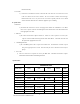
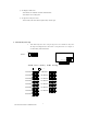
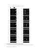
. Table Unit Address Setup 1. Table Unit Addresses can be setup to range from 1 to 50 tables on a single Main Unit. The Dip switch diagram below shows how to setup this feature. An example of Table #1 setup is listed below. Table # 1 : 8 SUN TELECOM INTL.
1 2 3 4 T T aa bb ll ee : U p U U nn ii tt : 5 6 7 5 6 7 8 A A dd dd rr ee ss ss S S ee tt uu pp D o w n 8 5 11 22 66 22 22 77 33 22 88 44 22 99 55 33 00 66 33 11 77 33 22 88 33 33 99 33 44 11 00 33 55 11 11 33 66 11 22 33 77 11 33 33 88 11 44 33 99 11 55 44 00 11 66 44 11 11 77 44 22 11 88 44 33 11 99 44 44 22 00 44 55 22 11 44 66 22 22 44 77 22 33 44 88 22 44 44 99 22 55 55 00 6 7 8 9 .
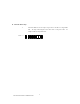
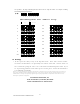
for operations. The Dip switch diagram below shows how to setup this feature. An example of adding units 2 through 20 setup is listed below. . 1: 1 2 3 4 5 6 7 C h e f / Management : U p : 5 6 7 8 Uni t Address Setup D o w n 8 5 11 11 11 22 11 22 33 11 33 44 11 44 55 11 55 66 11 66 77 11 77 88 11 88 99 11 99 11 00 22 00 6 7 8 10. Warnings 1. Do Not open outer body of any of the Expeditor Units.