
User's Manual

SUN TELECOM INTL. PROPRIETARY
5
5. 5. How to use ExpeditorHow to use Expeditor
1. Main Unit
1) Plug the 9V/1.5A adaptor into any 110v wall outlet. Once the unit is plugged into the power
supply, the red LED 9V Indicator will light.
2) Turn the power switch to ON. This switch is located on the bottom of the Main Unit body.
This will cause the red LED 5V Indicator to be lit.
3) When data is sent from the Table Unit a GREEN data LED will blink.
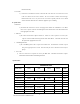
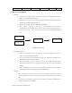
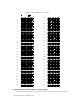
4) Once a request is sent from a Table Unit or an order information is sent from a
Chef/Management Unit, the Main Unit controls the flow of this information and sends it to
the proper Server Unit. Below is a diagram of the flow of information through the Main
Unit.
(Data transmission diagram)
2.
Chef/Management Unit
1) Plug the 9V/1.5A adaptor into any 110v wall outlet. Once the unit is plugged into the power
supply, the red LED 9V Indicator will light.
2) Turn the power switch to ON. This switch is located on the bottom of the Main Unit body.
This will cause the red LED 5V Indicator to be lit.
3) When a specific order is ready for a specific server, that servers button should be pressed.
This will send a notification to the specific Server Unit that an order is ready to be retrieved
in kitchen.
4) There is an OPTIONAL Group Call on the Chef/Management Unit allowing the Kitchen
Staff or Management to send a message to all Server Units simultaneously.
3.
Table Unit
1) Three AAA batteries are provided with each unit. These should be installed in accordance
with the instructions located in the battery well of the unit located on the bottom of the main
body.
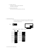
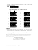
2) As shown below, the Menu Board lists the Server Call options. Individual establishments have
the option of altering these option displays.
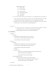
Chef Unit
Table Unit
Main Unit Server Unit