
User's Manual


English _ 11
INSTALLATION AND EXTERNAL CONNECTION
EXTERNAL CONNECTION
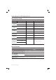
Wiring Diagram
Item
Cable Wiring
Power Supply Unit
Connect the DC+12V to the red line.
Connect GND to the black line.
Wiegand Connection
Connect the green line of the product to the Wiegand D0 input port of the controller.
Connect the white line of the product to the Wiegand D1 input port of the controller.
LED Control
To control the LED indicators, connect the yellow line to the output port (relay) of the controller.
Buzzer Control
To control the built-in buzzer, connect the blue line to the output port (relay) of the controller.
RS-232 Connection
Connect to the COM port of the PC. (Connect pin 2 of the DB-9 connector to the purple line; connect the
black line of the device (GND) to pin 5 of the DB-9 connector)
Tamper Connection
Connect the pink line of the product to the GND terminal of the controller.
Connect the light yellow wire of the product to the GND terminal of the controller.
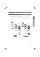
Blue
Yellow
RS-232(GND)
RS-232(TX)
Red Black
Buzzer Control In
LED Control In
DC +12V
GND
SSA-R1001V/SSA-R1101V
Wiegand Data 0 Out
Wiegand Data 1 Out
Green
White
Brown
Black
PC
CONTROLLER
POWER
Tamper Output(COM)
Tamper Output(NC)
Pink
Light yellow