
User's Manual


English _ 9
INSTALLATION AND EXTERNAL CONNECTION
installation and external connection
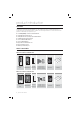
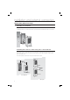
INSTALLATION
- Inserted in the doorframe / attached to the wall
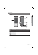
Two 6-32 or M3 holes are 3.3” (8.38 cm) away from each other vertically; between the two exists one 1/2” hole
through which the reader cables are arranged. The midway hole is located 1.7” (4.31cm) down from the upper hole.
(If the product is already installed, you can skip the follow step)
Insert the reader cables to the midway hole and fi x the reader module with two 6-32 or M3 screws.
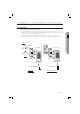
Insert the reader module into the appearance case and tighten the screw (M6x8mm) using the hex wrench.
1.
2.
3.
Electric Gang Box Mount
Wall Mount
Mullion Mount
Lower
Reader
Module
Bezel
6-32 hole
3.3”
(8.38cm)
Upper
6-32 hole
1/2”hole
1.7”
(4.31cm)
6-32 or M3 Screws
6-32 or M3 Screws
Reader
Module
Bezel
Gang Box
3mm Hex Wrench 3mm Hex Wrench