Standalone RFID Access Controller User Manual SSA-S1000V
Standalone RFID Access Controller User Manual Copyright ©2010 Samsung Techwin Co., Ltd. All rights reserved. Trademark is the registered logo of Samsung Techwin Co., Ltd. The name of this product is the registered trademark of Samsung Techwin Co., Ltd. Other trademarks mentioned in this manual are the registered trademark of their respective company. Restriction Samsung Techwin Co., Ltd shall reserve the copyright of this document.
safety information CAUTION RISK OF ELECTRIC SHOCK. DO NOT OPEN This symbol indicates that dangerous voltage consisting a risk of electric shock is present within this unit. This exclamation point symbol is intended to alert the user to the presence of important operating and maintenance (servicing) instructions in the literature accompanying the appliance. WARNING • To reduce the risk of fire or electric shock, do not expose this appliance to rain or moisture. WARNING 1.
safety information FCC Statement Caution : Any changes or modifications in construction of this device which are not expressly approved by the party responsible for compliance could void the user’s authority to operate the equipment. This device complies with part 15 of the FCC Rules. Operation is subject to the following two conditions: 1) This device may not cause harmful interference, and 2) This device must accept any interference received, including interference that may cause undesired operation.
contents Feature What’s included At a Glance Cable Color Scheme Cable Selection INSTALLATION AND EXTERNAL CONNECTION 10 10 11 Installation Bypass Diode Connection I/O Connection SYSTEM INITIALIZATION & BASIC OPERATIONS 13 13 14 14 Initializing the system by short-circuiting Basic Operations To register /delete Master ID To register/delete ID card TROUBLESHOOTING 15 TroubleShooting PRODUCT SPECIFICATIONS 16 Product Specifications 6 10 13 15 16 English English _ 5 CONTENTS 6 7 8 9 9 PRODUCT I
product introduction FEATURE This product is designed for use with one-door access control for security applications. With its compact design, you can install this product on the wall or a doorframe; Its epoxy adhesion and aluminium case guarantee shock-resistance as well as stable operation in a challenging environment.
WHAT’S INCLUDED Check if the following items are included in the product package. SSA-S1000V Bezel Main Module Master Card (x1) Keytag (x5) 3mm Hex Wrench (x1) 3.5 x 40mm Screws (x2) 3.
product introduction AT A GLANCE Front/Rear 4 3 5 SSA-S1000V 1 LED Displays the system operation status using red and green indicators. 2 Fixing Hole Fixing hole for wall-mounting. 3 Connection Cable Used to connect to the power or I/O cable. 4 Tamper Switch A tamper switch to detect falling from the wall. 5 Buzzer Piezo buzzer.
CABLE COLOR SCHEME Item Cable Color Signal Line Description Red DC+12V Black GND Yellow AUX INPUT#1 Blue Door Contact Sensor Green Exit Button Exit Button Connection Port Purple Alarm Out Alarm Device Connection Port White Door Lock Out Door Lock device connection port Pink TAMPER COM COM Port of Tamper Switch Light yellow TAMPER NC +12V supplied Input Earth-Grounding for Power Select a Lock Type Door Sensor Connection Port Output Tamper NC Port of Tamper Switch Gray Orange
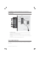
installation and external connection INSTALLATION 6-32 hole 6-32 or M3 Screws 1/2” hole 63.1mm 6-32 hole Reader Module 22.1mm 000V SSA-S1 Bezel 3mm Hex Wrench - On a doorframe or the wall 1. Drill a 1/2-inch (12.7 mm) hole onto the center of the doorframe or the wall where SSA-S1000V is installed, which makes room for the cable of the reader module. 2. Drill a 6-32 inch hole at the 43.1mm point straight higher from the center hole and at 22.1mm straight lower, respectively. 3.
I/O CONNECTION Input Connection INSTALLATION AND EXTERNAL CONNECTION DOOR CONTACT (blue) Door Contact Sensor EXIT BUTTON (green) Exit Button PUSH SSA-S1000V DC +12V GND (black) GND DC +12V (red) DC 12V(+) POWER - To connect the power supply unit 1. Connect the DC+12V to the red line. 2. Connect GND to the black line. - To connect the Door Contact Sensor 1. Connect the COM port of the sensor to the blue line. 2. Connect the NO port of the sensor with the GND line. - To connect the Exit Button 1.
installation and external connection Output Connection DOOR LOCK OUT (white) Door Lock ALARM OUT (purple) Alarm Device SSA-S1000V Lock Type Select (yellow) Cathode Anode 1N4004 ~ 1N4007 or equiv. DC +12V GND DC 12V(+) POWER - To connect the power supply unit 1. Connect the DC+12V to the red line. 2. Connect GND to the black line. - To connect the door lock device 1. Connect the plus(+) line of the lock device to DC+12V. 2. Connect the minus(-) line of the lock device to the white line.
system initialization & basic operations INITIALIZING THE SYSTEM BY SHORT-CIRCUITING Short-Circuit White 2. When you turn the product back on, all of the LED indicators turn red or green, repeat turning on/off twice before being completely turned off. Door Lock Green Exit Button Yellow Lock Type 3. In the power-off condition, all LED indicators turn green bottom up in sequence. SSA-S1000V 4. When you hear a beep 4 times, that indicates that the initialization is completed.
system initialization & basic operations TO REGISTER /DELETE MASTER ID 1. First turn off the product, and short-circuit two lines: purple line of Alarm Out and blue line of the Door Contact Sensor. SSA-S1000V Cable Blue 2. When you turn the product back on, you will hear the beep twice while all of the LED indicators turn red, and repeat turning on/off twice before being completely ON; then the Master card will be deleted. Yellow Green Short-Circuit 3.
troubleshooting TROUBLESHOOTING If the product does not function properly, please see the below for trouble shooting. SOLUTION PROBLEM 1) The Exit button does not work at all. 1) Check if the product works properly. - If the product works properly and you have the Master Card c Read the Master Card. d Read the card to delete. e Read the Master Card again to switch to normal mode. f For more information about deleting user cards, refer to the ID registration and deletion section in this manual.
product specifications PRODUCT SPECIFICATIONS Item SSA-S1000V Users 512 Users Power / Current DC 12V / Max.180mA Reading Time (Card) 30ms Door Open Time 5sec. (Fixed) Input Port 3ea: Exit Button, Door Sensor, Lock Type Select [Power fail Safe / Power Fail Secure] Output Port 2ea : TR Output / DC 12V. Rating Max. 300mA Alarm Output, DC 12V. Rating Max.
SALES NETWORK SAMSUNG TECHWIN CO., LTD. Samsungtechwin R&D Center, 701, Sampyeong-dong, Bundang-gu, Seongnam-si, Gyeonggi-do, Korea, 463-400 TEL : +82-70-7147-8740~60 FAX : +82-31-8018-3745 SAMSUNG TECHWIN AMERICA Inc. 1480 Charles Willard St, Carson, CA 90746, UNITED STATES Tol Free : +1-877-213-1222 FAX : +1-310-632-2195 www.samsungcctvusa.com www.samsungsecurity.com www.samsungtechwin.com SAMSUNG TECHWIN EUROPE LTD.