Standalone RFID Access Controller User Manual SSA-S2000V
Standalone RFID Access Controller User Manual Copyright ©2010 Samsung Techwin Co., Ltd. All rights reserved. Trademark is the registered logo of Samsung Techwin Co., Ltd. The name of this product is the registered trademark of Samsung Techwin Co., Ltd. Other trademarks mentioned in this manual are the registered trademark of their respective company. Restriction Samsung Techwin Co., Ltd shall reserve the copyright of this document.
safety information CAUTION RISK OF ELECTRIC SHOCK. DO NOT OPEN This symbol indicates that dangerous voltage consisting a risk of electric shock is present within this unit. This exclamation point symbol is intended to alert the user to the presence of important operating and maintenance (servicing) instructions in the literature accompanying the appliance. WARNING • To reduce the risk of fire or electric shock, do not expose this appliance to rain or moisture. WARNING 1.
safety information FCC Statement Caution : Any changes or modifications in construction of this device which are not expressly approved by the party responsible for compliance could void the user’s authority to operate the equipment. This device complies with part 15 of the FCC Rules. Operation is subject to the following two conditions: 1) This device may not cause harmful interference, and 2) This device must accept any interference received, including interference that may cause undesired operation.
contents 7 8 9 10 Features What’s included At a Glance Cable Color Scheme INSTALLATION AND EXTERNAL CONNECTION 11 12 12 14 Cable Selection Bypass Diode Connection I/O Connection External Reader Connection INITIALIZATION 15 16 16 Basic Operations Initialization Forced Initialization with External Line READER MODE SETUP 17 18 18 19 Reader Mode Setup (RF ONLY) Reader Mode Setup (RF + P/W) Reader Mode Setup (PIN ONLY) Reader Mode Setup (RF/PIN Combination Mode) Enabling Keypad Input for the Card Numbe
contents I/O TIME SETUP 28 28 29 29 30 30 31 31 32 To specify the output time if the card is authenticated To specify the output time if the card is not authenticated To specify the Duress TTL output To specify the alarm output for an input error of the Door contact Sensor To specify the alarm operation time for AUX 1 To specify the alarm operation time for AUX 2 To specify the alarm operation time for AUX 3 To activate or deactivate the door relay by the Door Contact Sensor ADVANCED SETTING 33 33 34 3
product introduction FEATURES Single Door Access Control You can use the RF card (SSA-C100,SSA-C110,SSA-C120) to control a single door. User Registration You can register a total of 512 cards including the Master Card. Keypad Registration SSA-S2000V is equipped with the built-in keypad that you can use to register, delete cards or configure various settings independently.
product introduction WHAT’S INCLUDED Check if the following items are included in the product package. SSA-S2000V Main Unit 3.5 x 40mm Screws (x4) 3.
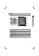
AT A GLANCE Front/Rear PRODUCT INTRODUCTION 3 4 5 SSA-S2000V 6 System Status LED Indicates the operation status of the system. Keypad Use this to configure or release settings as appropriate, or enter a card number. 3 TAMPER SWITCH A tamper switch to detect falling from the wall. 4 17-PIN Connector Used to connect to the power source or I/O cable. 5 Buzzer Piezo buzzer. 6 Fixing Hole Fixing hole for wall-mounting.
product introduction CABLE COLOR SCHEME Item Cable Color Signal Line Description Red DC +12V Power (+12V) Black GND(-) Earth-grounding for power Blue with white stripes NC(RL1) Door Relay NC Terminal Gray with red stripes COM(RL1) Door Control Relay (COM) Port White with red stripes NO(RL1) Door Relay NO port Purple with white stripes NC(RL2) Alarm Relay (NC) Port White COM(RL2) Alarm Relay (COM) Port Purple NO(RL2) Alarm Relay (NO) Port Orange with white stripes TTL TTL Output
installation and external connection CABLE SELECTION INSTALLATION AND EXTERNAL CONNECTION DC12V Power Supply SSA-S2000V RF Reader Item 1 Power (DC12V) DC Power This Product 2 Reader (power and data) External Reader This Product 3 Door Contact Sensor Exit Button Sensor Input Input This Product 4 J Door Lock, Alarm Device Lock (Alarm) This Product Sensor Input Lock/Alarm Cable Type Belden #9409, 18 AWG 2 Conductor, Unshielded Belden #9512, 22 AWG 4 Conductor, Shielded Belde
installation and external connection BYPASS DIODE CONNECTION If you connected an inductor (door locks or alarm device) to the output relay, there should occur a voltage surge while the inductor is turning on and off. If you do not connect a reverse diode to the relay, the surge voltage will cause damage to the electric circuit of the controller. To reduce this surge, it is recommended to connect a reverse diode between the devices. DC+ Cathode 1N4004 ~ 1N4007 or equiv.
Output Connection EXIT EXIT INSTALLATION AND EXTERNAL CONNECTION EXIT BUTTON CONTACT DOOR CONTACT AUX IN#1 CHIME +12V GND SSA-S2000V GND DOOR RELAY COM ALARM RELAY COM DOOR RELAY NO Cathode Anode PIR SENSOR ALARM RELAY NO CHIME BELL +12V 1N4004~1N4007 or equiv. GND DC 12V DOOR LOCK SIREN POWER SUPPLY - Door open (POWER FAIL SAFE) when the power is disconnected from the door lock (Door Relay) 1. Connect the relay COM line (gray with red stripes for locking the door) to DC +12V. 2.
installation and external connection EXTERNAL READER CONNECTION Wiegand DATA0(Pink) Wiegand DATA0(Sky blue) SSA-S2000V BlackRed+ GND DC+12V (+) (-) - Proximity Reader Connection 1. Connect the DC 12V(+) of the power supply unit to the plus (+) line of the reader. 2. Connect the GND(-) line of the power supply unit to the minus (-) line of the reader. 3. Connect the Wiegand data input line 0 of the proximity reader to the purple line. 4.
initialization BASIC OPERATIONS Initial Status While the product is working normally, the orange LED indicator blinks every one second. INITIALIZATION Predefined Operation for a Registered Card When reading a registered card, it opens the door with the melody. t Gj SSA-S2000V Exit Button Operation If you press the Exit button, the door will be opened. EXIT Predefined Operation for an Unregistered Card When reading an unregistered card, it produces an alarm with the melody for two seconds.
initialization INITIALIZATION If you have the Master Card registered, you can use it to initialize the device. 1. Present the Master Card to the device. 2. Press the button twice and press . Gj t SSA-S2000V 3. The system will restore the factory default settings with all LED indicators blinking. M Initializing the system will lose all data. SSA-S2000V If the product works abnormally, use initialization to restore the default settings. FORCED INITIALIZATION WITH EXTERNAL LINE 1.
reader mode setup - You can specify the operation mode for the device. - Once a mode is specified, it will not switch until you perform the initialization. - You must keep the Master Card in safe for later use as it is required for your change to the device settings. - If progression is halted for more than one minute during any of the following processes, the operation mode of the reader will return to the previous state.
reader mode setup READER MODE SETUP (RF + P/W) No Master Card or Master PIN is ever registered. If you remember the Master Card or the Master PIN was registered, initialize the product and try again. 1. When you turn on the product, all of the 3 LED indicators will flash with a beep. • No flashing of the 3 indicators denotes that the reader mode is already specified. SSA-S2000V 2. Press Button and Button in sequence and press . 3.
READER MODE SETUP (RF/PIN COMBINATION MODE) No Master Card or Master PIN is ever registered. If you remember the Master Card or the Master PIN was registered, initialize the product and try again. • No flashing of the 3 indicators denotes that the reader mode is already specified. SSA-S2000V 2. Press Button and Button in sequence and press . 3. Present a card that you want to register as the Master Card to the device. When the Master Card is registered, only the red LED indicator flashes. 4.
user management TO REGISTER CARDS IN RF ONLY MODE Ensure that you must have registered the Master Card and the device is specified in RF ONLY mode. 1. Present the Master Card to the device. When the mode is specified, only the green LED indicator flashes. Gj t and Button in sequence and press . 2. Press Button When the device enters Standby, only the red LED indicator flashes. 3. Present a card to the device, it will be registered with a beep. Repeat this step if you want to register multiple cards.
TO REGISTER CARDS IN PIN MODE Ensure that you must have registered the Master Card and the device is specified in PIN mode. 1. Enter the Master PIN number and press . When the mode is specified, only the green LED indicator flashes. SSA-S2000V 3. If you enter a user number (4-6 digits) to register and press number will be registered with a beep. Repeat this step if you want to register multiple PIN numbers. , the PIN 4.
user management TO DELETE A REGISTERED CARD OR PIN NUMBER Ensure that you must have registered the Master Card or the Master PIN number and the device is specified in a certain mode. This is applicable in all modes. 1. Enter the Master Card or Master PIN. When the mode is specified, only the green LED indicator flashes. Gj t and Button in sequence and press . 2. Press Button When the device enters Standby, only the red LED indicator flashes. SSA-S2000V 3. Present a card or PIN number to delete.
basic setup DURESS ALARM If you are forced to open the door under the control of a criminal such as a robber, enter the predefined password with the number of your registered card (or PIN), which outputs the emergency TTL signal. 1. Present the Master Card to the device. and Button in sequence and press Gj t 3. Enter the two-digit Duress code and press . . • The default code is set to “00”. However, the number “77” can not be used because it is set for the Secure mode.
basic setup TO SPECIFY THE KEYPAD INPUT SUSPENSION TIME IF THE RETRY COUNT WITH AN UNREGISTERED ID EXCEEDS THE LIMIT 1. Present the Master Card to the device. and Button in sequence and press . 3. Enter the two-digit keypad input suspension time (unit: minute) and press . Gj t 2. Press Button SSA-S2000V • The default is set to “01”. You can specify a time from 01 to 99 minutes.
TO SPECIFY THE OPERATION TIME OF THE DOOR CONTACT SENSOR The Door Contact sensor detects the opening of the door. If the door is forcibly opened by an unregistered user, the Door Contact Sensor will perform the predefined alarm operation after the set time. (For setting the alarm operation time, refer to the alarm output for an input error of the Door Contact Sensor on page 30.) BASIC SETUP 1. Present the Master Card to the device. and Button . 3.
basic setup TO SPECIFY THE ALARM OUTPUT PORT FOR THE DISMANTLED DEVICE Specify the alarm type for the dismantled device. The alarm rings from the dismantlement of the device to the authentication of the Master Card or a registered card. 1. Present the Master Card to the device. 2. Press Button and Button in sequence and press . • The default is set to “02” (alarm). For the alarm output port settings, refer to the output port table on page 28. Gj t 3. Provide the alarm output port and press .
TO SET OR RELEASE THE QUICK MODE The QUICK mode is applicable to RF ONLY mode (01) and PIN ONLY mode (03) and RF/PIN combination mode (05), which enables you to open the door by simply pressing without the need of the PIN number. (This is useful for the normal business hours when the door entries and exits occur frequently.) BASIC SETUP 1. Present the Master Card to the device. 2. Press Button and Button in sequence and press .
I/O time setup ❖ Output Port Setting Table You must specify the port settings using whatever combination of the followings if you want the device to operate in Secure mode or normal + Secure mode.
TO SPECIFY THE OUTPUT TIME IF THE CARD IS NOT AUTHENTICATED You can specify the output time if an unregistered card or PIN number fails in getting authenticated. 1. Present the Master Card to the device. twice and press . • If you want the alarm relay alone to operate in normal and Secure modes for an unauthenticated card, select the < > buttons and press . 4. Enter the two-digit door relay output time and press 5. Enter the two-digit alarm relay output time and press 6.
I/O time setup TO SPECIFY THE ALARM OUTPUT FOR AN INPUT ERROR OF THE DOOR CONTACT SENSOR You can specify the output port and operation time if an error occurs from the Door Contact Sensor. You must have specified the operation time of the Door Contact Sensor. (Refer to “To specify the operation time of the Door Contact Sensor” on page 25.) 1. Present the Master Card to the device. 2. Press Button and Button in sequence and press .
TO SPECIFY THE ALARM OPERATION TIME FOR AUX 2 1. Present the Master Card to the device. 2. Press Button and Button in sequence and press . . 5. Enter the two-digit alarm relay output time and press . SSA-S2000V • You can specify a two-digit time from 00 to 99 seconds. • By default, all output times are set to “00”. M Other output ports that are not specified for the output mode will not be activated.
I/O time setup TO ACTIVATE OR DEACTIVATE THE DOOR RELAY BY THE DOOR CONTACT SENSOR You can set the Door Contact Sensor to control the door lock. This is to allow the Door Contact Sensor to control the door relay where the sensor keeps the door relay active from the normal opening of the door to its closing. This is useful when the door stays open with just one authentication. 1. Present the Master Card to the device. 2. Press Button and Button in sequence and press .
advanced setting TO SPECIFY THE TTL OUTPUT OPERATION MODE This is to switch the TTL output from LOW (0V) to HIGH (5V) when it is activated. 1. Present the Master Card to the device. in sequence and press . • To release the setting, repeat Step 1 above, select the < M > buttons and press SSA-S2000V . The default is set to “switch from HIGH(5V) to LOW(0V)”. SSA-S2000V TO SET THE CHIME BELL FUNCTION You can specify the use of the chime bell. Use the chime bell in the TTL level (5V) for this purpose.
advanced setting TO SPECIFY THE CHIME BELL OPERATION TIME You can specify the chime bell operation time. 1. Present the Master Card to the device. and Button in sequence and press . Gj t 2. Press Button SSA-S2000V . 3. Specify the two-digit operation time (unit: second) and press M The default is set to “05” second. You can specify a time from 00 to 99 seconds.
TO SPECIFY THE INPUT MODE FOR AUX 2 You can specify an operation for the auxiliary port 2 when it switches from LOW (0V) to HIGH (5V). 1. Present the Master Card to the device. and Button in sequence and press > buttons and press . Gj t • To release the setting, press the < . SSA-S2000V M The default is set to “switch from HIGH(5V) to LOW(0V)”.
advanced setting TO SPECIFY THE INPUT MODE FOR THE EXIT BUTTON You can specify an operation for the Exit button when it switches from LOW (0V) to HIGH (5V). 1. Present the Master Card to the device. 2. Press Button and Button and Button > buttons and press . Gj t • To release the setting, press the < . SSA-S2000V M The default is set to “switch from HIGH(5V) to LOW(0V)”.
additional features MUTE You can mute the keypad tone or melody in normal operation. 1. Present the Master Card to the device. and Button in sequence and press . M Gj t • To release the setting, repeat Step 1 above, select the < > buttons and press . SSA-S2000V By default, it is set to “enabled”. SSA-S2000V TO SPECIFY THE USE OF THE TAMPER ALARM You can maintain the alarm setup in normal operation and release it in case of a service repair requiring the dismantlement of the device.
additional features TO CHECK THE OUTPUT SPECIFIED FOR A REGISTERED CARD USER You can check the output setting that you specified in “To specify the output time if the card is authenticated”. (See page 28.) 1. Present the Master Card to the device. and Button in sequence and press . Gj t 2.
TO CHECK THE OUTPUT SPECIFIED FOR THE DOOR CONTACT SENSOR ALARM You can check the output setting that you specified in “To specify the alarm output for an input error of the Door contact Sensor”. (See page 30.) and Button in sequence and press . Gj t 2. Press Button SSA-S2000V SSA-S2000V TO CHECK THE OUTPUT SPECIFIED FOR AUX 1 You can check the output setting that you specified in “To specify the alarm operation time for AUX 1”. (See page 30.) 1. Present the Master Card to the device.
additional features TO CHECK THE OUTPUT SPECIFIED FOR AUX 2 You can check the output setting that you specified in “To specify the alarm operation time for AUX 2”. (See page 31.) 1. Present the Master Card to the device. and Button in sequence and press . Gj t 2. Press Button SSA-S2000V SSA-S2000V TO CHECK THE OUTPUT SPECIFIED FOR AUX 3 You can check the output setting that you specified in “To specify the alarm operation time for AUX 3”. (See page 31.) 1.
other information INITIAL VALUES This product operates in the following initial values: For changing the settings or registering/deleting the user card, refer to the applicable section in this document. 1) Entry permitted for a registered card - The door control relay operates for 3 seconds. OTHER INFORMATION - The green LED indicator flashes for 3 seconds. 2) Entry denied for an unregistered card - The alarm relay operates for 2 seconds. - The red LED indicator flashes for 2 seconds.
other information FUNCTION CODES NO.
Code Number Function Item 29 51 Turn off the sound 30 52 Turn on the sound 31 60 To specify the keypad input suspension time if the retry count with an unregistered ID exceeds the limit 32 61 Sense if AUX 1 switches from L to H 33 62 Sense if AUX 1 switches from H to L 34 63 Sense if AUX 2 switches from L to H 35 64 Sense if AUX 2 switches from H to L 36 65 Sense if AUX 3 switches from L to H 37 66 Sense if AUX 3 switches from H to L 38 67 Sense if the Exit button switches fro
troubleshooting TROUBLESHOOTING If the product does not function properly, please see the below for trouble shooting. PROBLEM ACTION When I turn on the product, it does not recognize the card with just the 3 LED indicators blinking. Check if the product is installed properly and works normally. - In the initial setup of the product or after it is initialized Set the operation mode and register the Master card and user cards as usual because the product is in the initial state.
PROBLEM I can not register an additional user card (or PIN). ACTION 1) English _ 45 TROUBLESHOOTING Check if the product is installed properly and works normally. - In the initial setup of the product or after it is initialized Set the operation mode and register the Master card and user cards as usual because the product is in the initial state.
troubleshooting PROBLEM ACTION The user card (or PIN) is not deleted. Check the operation status of the product 1) Check if the product works properly.
PROBLEM ACTION SSA-S2000V can recognize a presented RF card but can not recognize the RF card number using the keypad. Check if the buzzer sounds when you press a key. - If you hear the buzzer sound c Master Card (or (PIN): 4 ~ 6 digits (Mode 03 or 05) + ENT) d Enter the command to enable the keypad input: 73 + ENT e For more information, refer to the section of enabling or disabling the keypad input for a card number in the user manual.
troubleshooting PROBLEM The external reader can the RF card but the RF card data will not be transferred to SSA-S2000V or irrelevant data is transferred. ACTION 1) 2) Check if the external reader is connected to SSA-S2000V properly. Check if the external reader works normally. - Check the connection cable between the external reader and SSA-S2000V for any disconnection or short-circuit. - Check if there occurs a noise on the connection cable between the external reader and SSA-S2000V.
product specifications PRODUCT SPECIFICATIONS Item SSA-S2000V 512 Users Power / Current DC 12V / Max.180mA Reader Port External Reder Port 1ea : 26bit Wiegand for Exit Reading Time (Card) 30ms Door Open Time 00~99 Sec. (Default 3Sec.) Input Port 5ea : Exit Button, Door Sensor, Aux#1, #2, #3 2ea : 2 Form-C Relay Output (COM, NO, NC) / DC12~18V, Rating Max.2A Output Port 1ea : Chime Bell Output / DC5V, Rating Max.500mA 1ea : TTL Output / DC5V, Rating Max.
SALES NETWORK SAMSUNG TECHWIN CO., LTD. Samsungtechwin R&D Center, 701, Sampyeong-dong, Bundang-gu, Seongnam-si, Gyeonggi-do, Korea, 463-400 TEL : +82-70-7147-8740~60 FAX : +82-31-8018-3745 SAMSUNG TECHWIN AMERICA Inc. 1480 Charles Willard St, Carson, CA 90746, UNITED STATES Tol Free : +1-877-213-1222 FAX : +1-310-632-2195 www.samsungcctvusa.com www.samsungsecurity.com www.samsungtechwin.com SAMSUNG TECHWIN EUROPE LTD.