ITEM #0451798, 0451799 52 IN CLASSIC STYLE CEILING FAN MODEL #40081, 40082 Harbor Breeze® is a registered trademark of LF, LLC. All Rights Reserved. Español p. 22 LISTED FOR WET LOCATION ATTACH YOUR RECEIPT HERE Serial Number _________________________ Purchase Date _________________________ Questions, problems, missing parts? Before returning to your retailer, call our customer service department at 1-800-643-0067, 8 a.m. - 6 p.m., EST, Monday - Thursday, 8 a.m. - 5 p.m., EST, Friday.
TABLE OF CONTENTS Package Contents. . . . . . . . . . . . . . . . . . . . . . . . . . . . . . . . . . . . . . . . . . . . . . . . . . . . . . . . . . . . . . . . . 3 Hardware Contents. . . . . . . . . . . . . . . . . . . . . . . . . . . . . . . . . . . . . . . . . . . . . . . . . . . . . . . . . . . . . . . . 4 Safety Information. . . . . . . . . . . . . . . . . . . . . . . . . . . . . . . . . . . . . . . . . . . . . . . . . . . . . . . . . . . . . . . . . 5 Preparation . . . . . . . . . . . . . . . . .
PACKAGE CONTENTS A B C D E H I F G PART A B C D E F G H I J J DESCRIPTION Downrod Canopy (preassembled to Mounting Bracket (C)) Mounting Bracket Yoke Cover Motor Assembly Switch Housing (preassembled to Motor Assembly (E)) Switch Housing Cap (preassembled to Switch Housing (F)) Blade Arm Blade Canopy Cover (preassembled to Canopy (B)) 3 QUANTITY 1 1 1 1 1 1 1 5 5 1 Lowes.
HARDWARE CONTENTS AA BB CC Motor Screw Qty. 10 (preassembled to Motor Assembly (E)) + 1 extra Wire Connector Qty. 3 + 1 extra Pull Chain Extension Qty. 1 FF GG HH II JJ Motor Housing Set Screw Qty. 2 (preassembled to Motor Assembly (E)) Closemount Screw Qty. 3 (preassembled to Motor Assembly (E)) Mounting Bracket Screw Qty. 4 (preassembled to Mounting Bracket (C)) Blade Screw Qty. 5 + 1 extra Blade Washer Qty. 5 + 1 extra KK LL Spring Washer Qty.
SAFETY INFORMATION Please read and understand this entire manual before attempting to assemble, operate or install the product. • Before you begin installing the fan, disconnect the power by removing fuses or turning off the circuit breakers. • Make sure that all electrical connections comply with local codes, ordinances, the National Electrical Code, and ANSI/NFPA 70-199. Hire a qualified electrician or consult a do-it-yourself wiring handbook if you are unfamiliar with installing electrical wiring.
SAFETY INFORMATION CAUTION: Read all instructions and safety information before installing your new fan. Review the accompanying assembly diagrams. CAUTION: Be sure the outlet box is properly grounded or that a ground (green or bare) wire is present. CAUTION: Carefully check all screws, bolts, and nuts on the fan motor assembly to ensure they are secured. PREPARATION Before beginning the assembly of this product, ensure all parts are present.
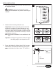
INITIAL INSTALLATION 1. Turn off the circuit breakers and the wall switch to the fan supply line leads. 1 DANGER: Failure to disconnect the power supply prior to installation may result in serious injury or death. 2. Determine the mounting method to use. Helpful Hint: Downrod mounting is best suited for ceilings 8 ft. or higher. For taller ceilings you may want to use a longer downrod (not included). Angle mounting is best suited for angled or vaulted ceilings.
INITIAL INSTALLATION 4. Remove the two mounting bracket screws (HH) from the round holes of the canopy (B). Set aside for later use. Detach mounting bracket (C) from canopy (B). 4 C Hardware Used HH 5. HH Mounting Bracket Screw x2 B Feed black, blue and white wires up from the plug on the mounting bracket (C) up through the hole in the top. 5 C 6. Remove and discard the three rubber stoppers and the five plastic spacers from the underside of the motor assembly (E).
STANDARD OR ANGLE MOUNTING INSTRUCTIONS WARNING: To reduce the risk of fire, electrical shock, or personal injury, wire connectors provided with this fan are designed to accept only one 12-gauge house wire and two lead wires from the fan. If your house wire is larger than 12 gauges and there is more than one house wire to connect to the two fan lead wires, consult an electrician for the proper size wire connectors to use. BB 2. 3 Hardware Used 3.
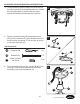
STANDARD OR ANGLE MOUNTING INSTRUCTIONS 4. Feed green/bare (ground) supply wire down through the hole in the top of the mounting bracket (C). Secure the mounting bracket (C) to the outlet box using screws and washers provided with the outlet box. 4 C 5. Remove the downrod clip (DD) and downrod pin (EE) from the downrod (A). Then partially loosen the motor housing set screws (FF) in the yoke at the top of the motor assembly (E). A DD Hardware Used DD 5 EE x1 Downrod Clip FF A 6.
STANDARD OR ANGLE MOUNTING INSTRUCTIONS 7. Slide the downrod (A) into the yoke of the motor assembly (E), align the holes, and re-install the downrod clip (DD) and downrod pin (EE). Then tighten the motor housing set screws (FF). 7 Hardware Used DD Downrod Clip x1 EE Downrod Pin x1 FF Motor Housing Set Screw A DD E EE FF x2 8. Carefully lift the downrod (A) onto the mounting bracket (C). Rotate the downrod (A) until the slot on the downrod (A) engages the tab on the mounting bracket (C).
CLOSEMOUNT INSTRUCTION WARNING: To reduce the risk of fire, electrical shock, or personal injury, wire connectors provided with this fan are designed to accept only one 12-gauge house wire and two lead wires from the fan. If your house wire is larger than 12 gauges and there is more than one house wire to connect to the two fan lead wires, consult an electrician for the proper size wire connectors to use. BB 2.
CLOSEMOUNT INSTRUCTIONS 4. Secure the mounting bracket (C) to the outlet box using screws and washers provided with the outlet box. 4 C 5. Remove the canopy cover (J) from the bottom of the canopy (B). 1 5 Helpful Hint: Closemount-style mounting is more suitable for ceilings lower than 8 ft. high. The downrod (A) and canopy cover (J) are not used in this type of installation. B J 6. Remove closemount screws (GG) from the top of the motor assembly (E).
CLOSEMOUNT INSTRUCTIONS 7. Raise the fan and place the canopy (B) on the hook on the mounting bracket (C). 7 C B 14 Lowes.
FINAL INSTALLATION Note Downrod (A) is shown/referenced, but instructions are applicable to both standard and closemount-style installations. 1. Wrap the wire harness coming from the downrod 1 (A) around the hooks on the back of the mounting bracket (C). C Note: Extra wire harness length accommodates longer downrods (sold separately). Hook 2. Connect the pin connector from the mounting bracket (C) to the pin connector at the end of the wire harness. A 2 C A 3.
FINAL INSTALLATION 4. Secure the canopy (B) with mounting bracket screws (HH) previously removed (Step 4, page 8). Tighten all mounting bracket screws (HH) securely. 4 Hardware Used HH 5. B Mounting Bracket Screw x4 Align blade arm (H) studs with their corresponding holes in the blade (I) and then insert the blade screw (II), blade washer (JJ) and rubber washer (LL) to attach one blade arm (H) to a blade (I). Tighten the blade screw (II). Repeat for each blade (I).
FINAL INSTALLATION 7. Attach the pull chain extension (CC) or custom pull chain extension (not included) to the fan pull chain. 7 Hardware Used Pull Chain Extension x1 CC b o r Br e e 1 Fan Fan PullPull Chain Use the fan reverse switch, located on the switch housing (F) to optimize your fan for seasonal performance. Chain A ceiling fan will allow you to raise your thermostat setting in summer and lower your thermostat setting in winter without feeling a difference in your comfort. 2B.
CARE AND MAINTENANCE At least twice each year, lower the canopy to check the downrod assembly, and then tighten all screws on the fan. Clean the motor housing with only a soft brush or lint-free cloth to avoid scratching the finish. Clean the blades with a lint-free cloth. You may occasionally apply a light coat of furniture polish to wood blades for added protection. Important Shut off the main power supply before you begin any maintenance task. Do not use water or a damp cloth to clean the fan.
TROUBLESHOOTING PROBLEM There is excessive wobbling. POSSIBLE CAUSE 1. The blades and/or blade are loose. CORRECTIVE ACTION 1. Check and tighten all screws that hold the fan blades to the blade arms and the blade arms to the motor. 2. The blades are unbalanced. 2. Switch one blade with a blade from the opposite side. Or balance the fan using a balancing kit (not supplied). 3. The fan mounting is not secure. 3. Turn off the power.
LIFETIME LIMITED WARRANTY The manufacturer warrants this fan to be free from defects in workmanship and materials present at time of shipment from the factory for a lifetime from the date of purchase by the original purchaser. The retailer also warrants that all other fan parts, excluding any glass or plexiglas blades, to be free from defects in workmanship and material at the time of shipment from the factory for a period of one year after the date of purchase by the original purchaser.
REPLACEMENT PARTS LIST For replacement parts, call the customer service department at 1-800-643-0067, 8 a.m. - 6 p.m., EST, Monday - Thursday, 8 a.m. - 5 p.m., EST, Friday. PART # PART A B C H I HW DESCRIPTION Downrod Canopy Mounting Bracket Blade Arm Blade Hardware Kit A H B #0451798 #0451799 0451798-A 0451798-B 0451798-C 0451798-H 0451798-I 0451798-HW 0451799-A 0451799-B 0451799-C 0451799-H 0451799-I 0451799-HW C I HW Printed in China Harbor Breeze® is a registered trademark of LF, LLC.
ARTÍCULO #0451798, 0451799 VENTILADOR DE TECHO CLASSIC STYLE DE 132,08 CM MODELO #40081, 40082 Harbor Breeze® es una marca registrada de LF, LLC. Todos los derechos reservados. HOMOLOGADO PARA LUGARES HÚMEDOS ADJUNTE SU RECIBO AQUÍ Número de serie _________________________ Fecha de compra _________________________ ¿Preguntas, problemas, piezas faltantes? Antes de volver a la tienda, llame a nuestro Departamento de Servicio al Cliente al 1-800-643-0067, de lunes a jueves de 8 a.m. a 6 p.m.
ÍNDICE Contenido del paquete . . . . . . . . . . . . . . . . . . . . . . . . . . . . . . . . . . . . . . . . . . . . . . . . . . . . . . . . . . . . 24 Aditamentos. . . . . . . . . . . . . . . . . . . . . . . . . . . . . . . . . . . . . . . . . . . . . . . . . . . . . . . . . . . . . . . . . . . . . 25 Información de seguridad . . . . . . . . . . . . . . . . . . . . . . . . . . . . . . . . . . . . . . . . . . . . . . . . . . . . . . . . . . 26 Preparación. . . . . . . . . . . . . . . . . . . . . . . . . .
CONTENIDO DEL PAQUETE A B C D E H I F G PIEZA A B C D E F G H I J J DESCRIPCIÓN Varilla Base (preensamblado en la abrazadera de montaje (C)) Abrazadera de montaje Cubierta de la horquilla Ensamble del motor Carcasa del interruptor (preensamblada en el ensamblaje del motor (E)) Tapa de la carcasa del interruptor (preensamblado en la tapa de la carcasa del interruptor (F)) Brazo del aspa Aspa Cubierta de la base (preensamblada en la base (B) CANTIDAD 1 1 1 1 1 1 Lowes.
ADITAMENTOS AA Tornillo del motor Cant. 10 (preensamblado en la carcasa del motor [A]) y 1 adicional FF Tornillo de ajuste de la carcasa del motor Cant. 2 (preensamblado en el ensamblaje del motor (E)) KK Arandela de resorte Cant. 10 (preensamblado en la tornillo del motor (AA)) y 1 adicional BB Conector de cables Cant. 3 y 1 adicional GG Tornillo de montaje cerrado Cant. 3 (preensamblado en el ensamblaje del motor (E)) CC Extensión para la cadena de tiro Cant.
INFORMACIÓN DE SEGURIDAD Lea y comprenda completamente este manual antes de intentar ensamblar, usar o instalar el producto. • Antes de comenzar a instalar el ventilador, desconecte la alimentación eléctrica; para esto retire los fusibles o coloque el interruptor de circuito en la posición de apagado. • Asegúrese de que todas las conexiones eléctricas cumplan con los códigos y ordenanzas locales, el National Electrical Code (Código Nacional de Electricidad) y la norma ANSI/NFPA 70-199.
INFORMACIÓN DE SEGURIDAD PRECAUCIÓN: Lea todas las instrucciones y la información de seguridad antes de instalar el nuevo ventilador. Revise los diagramas de ensamblaje adjuntos. PRECAUCIÓN: asegúrese de que la caja de salida cuente con la puesta a tierra adecuada o de que haya un conductor (verde o desnudo) de tierra. PRECAUCIÓN: Revise cuidadosamente todos los tornillos, pernos y tuercas del ensamble del motor del ventilador para comprobar que estén seguros.
INSTALACIÓN INICIAL 1. Gire las abrazaderas de circuito y el interruptor de pared hacia los conductores de la línea de suministro del ventilador. 1 PELIGRO: si no interrumpe el suministro de electricidad antes de la instalación, pueden producirse lesiones graves o la muerte. 2. Determine los métodos de instalación que utilizará. Sugerencia útil: el montaje de varilla es más apropiado para los techos de 2,44 m de alto o de mayor altura.
INSTALACIÓN INICIAL 4. Retire los dos tornillos de la abrazadera de montaje (HH) de los orificios redondos de la base. Déjelos a un lado para usarlos posteriormente. Retire la abrazadera de montaje (C) de la base (B). Hardware Used Tornillo de la HH abrazadera de montaje 5. 4 C HH x2 B Pase el conductor negro, azul y el conductor blanco del enchufe en la abrazadera de montaje (C) hacia el orificio en la parte superior. 5 C 6.
INSTRUCCIONES DE MONTAJE EN ÁNGULO Y ESTÁNDAR Blanco Negro Azul ADVERTENCIA: para reducir el riesgo de incendios, descargas eléctricas o lesiones personales, los conectores de cables proporcionados con este ventilador están diseñados para soportar solo un cable de la casa de calibre 12 y dos cables conductores del ventilador.
INSTRUCCIONES DE MONTAJE EN ÁNGULO Y ESTÁNDAR 4. Pase el conductor de suministro verde/desnudo (de puesta a tierra) por el orificio en la parte superior de la abrazadera de montaje (C). Asegure la abrazadera de montaje (C) a la caja de salida con los tornillos y las arandelas que incluye la caja de salida. 4 C 5. Retire el pasador de la varilla (EE) y el sujetador de la varilla (DD) de la varilla de (A).
INSTRUCCIONES DE MONTAJE EN ÁNGULO Y ESTÁNDAR 7. Deslice la varilla (A) por la horquilla del ensamblaje 7 del motor (E), alinee los orificios y vuelva a instalar el sujetador (EE) y el pasador (FF) de la varilla. Luego vuelva a apretar los tornillos de ajuste de la carcasa del motor (GG). Aditamentos utilizados A DD DD Pasador de la varilla x1 EE Sujetador de la varilla x1 FF Tornillo de ajuste de la carcasa del motor E EE FF x2 8.
INSTRUCCIONES PARA MONTAJE CERRADO Verde Blanco Negro Azul ADVERTENCIA: para reducir el riesgo de incendios, descargas eléctricas o lesiones personales, los conectores de cables proporcionados con este ventilador están diseñados para soportar solo un cable de la casa de calibre 12 y dos cables conductores del ventilador.
INSTRUCCIONES PARA MONTAJE CERRADO 4. Asegure la abrazadera de montaje (C) a la caja de salida con los tornillos y las arandelas que incluye la caja de salida. 4 C 5. Retire la cubierta de la base (J) de la parte inferior de la base (B). 1 5 Consejo útil: El estilo de montaje cerrado es más adecuado para los techos de menos de 2,44 m (8 pies) de alto. La varilla, la bola para colgar y la cubierta de la base no se utilizan en este tipo de instalación. B J 6.
INSTRUCCIONES PARA MONTAJE CERRADO 7. Levante el ventilador y coloque la base (B) en el gancho de la abrazadera de montaje (C). 7 C B Lowes.
INSTALACIÓN FINAL Nota: Se hace referencia/se muestra la varilla (A), pero las instrucciones se aplican a las instalaciones estándar y a las de montaje cerrado. 1. Envuelva el arnés de cableado que proviene de 1 la varilla (A) alrededor de los ganchos en la parte posterior de la abrazadera de montaje (C). C Nota: El arnés de cableado más largo se adapta a varillas más largas (se vende por separado). Gancho A 2.
INSTALACIÓN FINAL 4. Asegure la base (B) con los tornillos del soporte de montaje (HH) que retiró anteriormente. Apriete firmemente los cuatro tornillos del soporte de montaje (HH). 4 B Aditamentos utilizados HH 5. HH Tornillo de la abrazadera de montaje x4 Alinee los montantes del brazo del aspa (H) con los respectivos orificios en el aspa (I) y luego inserte el tornillo del aspa (II), la arandela de goma (LL) y la arandela del aspa (JJ) para fijar un brazo de aspa (H) a un aspa (I).
INSTALACIÓN FINAL 7. Conecte la extension para la cadena de tiro (CC) o las extension para la cadena de tiro personalizadas (no incluidas) con la cadena de tiro del ventilador. 7 Aditamentos utilizados Extensión para la cadena de tiro x1 CC b o r Br e e 1 Utilice el interruptor de reversa del ventilador, ubicado en la carcasa del interruptor del soporte del juego de iluminación (F), para optimizar el rendimiento de su ventilador según la estación del año.
CUIDADO Y MANTENIMIENTO Al menos dos veces al año, baje la base para revisar en ensamble de la varilla, y luego apriete todos los tornillos en el ventilador. Limpie la carcasa del motor solo con un cepillo suave o un paño sin pelusas para evitar rayar el acabado. Limpie las aspas con un paño sin pelusas. De vez en cuando puede aplicar una fina capa de cera para muebles en las aspas de madera para darles más protección.
SOLUCIÓN DE PROBLEMAS PROBLEMA CAUSA POSIBLE 1. Una o varias aspas están flojas. 2. Las aspas no están equilibradas. Hay un tambaleo excesivo. ACCIÓN CORRECTIVA 1. Revise y apriete todos los tornillos que sostienen las aspas del ventilador en los brazos de las aspas y en el motor. 2. Intercambie un aspa con otra del lado opuesto. O equilibre el ventilador mediante el kit de equilibrio (no se incluye). 3. El montaje del ventilador no está asegurado. 4. The fan is too close to the vaulted ceiling. 5.
GARANTÍA LIMITADA DE POR VIDA El fabricante garantiza que este ventilador no presenta defectos de mano de obra ni de materiales en el momento del transporte desde la fábrica durante un período de por vida a partir de la fecha de compra del comprador original.
LISTA DE PIEZAS DE REPUESTO Para obtener piezas de repuesto, llame a nuestro Departamento de Servicio al Cliente al 1-800-643-0067, de lunes a viernes de 8 a.m. a 6 p.m., y los viernes de 8 a.m. a 5 p.m., hora estándar del Este.