ITEM #0176493, 0179178, 0922357, 0922356 LANSING CEILING FAN MODEL #40948, 40949, 41108, 41107 Español p. 21 Harbor Breeze® is a registered trademark of LF, LLC. All Rights Reserved. ATTACH YOUR RECEIPT HERE Purchase Date _________________________ Questions, problems, missing parts? Before returning to your retailer, call our customer service department at 1-800-643-0067, 8 a.m. - 6 p.m., EST, Monday - Thursday, 8 a.m. - 5 p.m., EST, Friday.
TABLE OF CONTENTS Package Contents. . . . . . . . . . . . . . . . . . . . . . . . . . . . . . . . . . . . . . . . . . . . . . . . . . . . . . . . . . . . . . . . . 3 Hardware Contents. . . . . . . . . . . . . . . . . . . . . . . . . . . . . . . . . . . . . . . . . . . . . . . . . . . . . . . . . . . . . . . . 4 Safety Information. . . . . . . . . . . . . . . . . . . . . . . . . . . . . . . . . . . . . . . . . . . . . . . . . . . . . . . . . . . . . . . . . 5 Preparation . . . . . . . . . . . . . . . . .
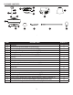
PACKAGE CONTENTS D R A B E H E C F F P Q G I I J O S PART A B C D E F G H I J K L M N O P Q R S K K L M M DESCRIPTION Downrod Downrod Pin (preassembled to Downrod [A]) Downrod Clip (preassembled to Downrod [A]) Mounting Bracket (preassembled to Canopy [E]) Canopy Canopy Cover (preassembled to Canopy [E]) Light Kit Glass Shade Motor Assembly Fitter Plate (preassembled to Motor Assembly [I]) Yoke Cover Blade Arm Blade Bulb Motor Screw (preassembled to Motor Assembly [I]) Set Screw (preasse
HARDWARE CONTENTS CC DD Wire Connector Qty. 3 + 1 extra Blade Screw Qty. 15 + 1 extra Blade Washer Qty. 15 + 1 extra XX Motor Screw 1 extra 4 b o r Br e e ar H H ar ze BB ze AA b o r Br e e Pull Chain Extension Qty.
SAFETY INFORMATION Please read and understand this entire manual before attempting to assemble, operate, or install the product. • Before you begin installing the fan, disconnect the power by removing fuses or turning off the circuit breakers. • Make sure that all electrical connections comply with local codes, ordinances, the National Electrical Code, and ANSI/NFPA 70-199. Hire a qualified electrician or consult a do-it-yourself wiring handbook if you are unfamiliar with installing electrical wiring.
SAFETY INFORMATION CAUTION: Read all instructions and safety information before installing your new fan. Review the accompanying assembly diagrams. CAUTION: Be sure the outlet box is properly grounded or that a ground (green or bare) wire is present. CAUTION: Carefully check all screws, bolts and nuts on the fan motor assembly to ensure they are secured. PREPARATION Before beginning the assembly of this product, ensure that all parts are present.
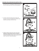
INITIAL INSTALLATION 1. Turn off the circuit breakers and the wall switch to the fan supply line leads. 1 DANGER: Failure to disconnect the power supply prior to installation may result in serious injury or death. 2. Determine the mounting method to use. Standard Mounting is best suited for ceilings 8 ft. or higher. For taller ceilings you may want to use a longer downrod (sold separately). 2 Angle mounting is best suited for angled or vaulted ceilings.
INITIAL INSTALLATION 4. Loosen all four mounting bracket screws (R), then completely remove the two mounting bracket screws (R) from the round holes of canopy (E). Set aside for later use. 4 Detach mounting bracket (D) from canopy (E). D D R E E 5. Attach mounting bracket (D) to outlet box (not included) using screws and washers provided with the outlet box.
STANDARD OR ANGLED MOUNTING INSTRUCTIONS 1. Remove the downrod clip (C) and downrod pin (B) from the downrod (A). Then partially loosen the set screws (P) in the yoke at the top of the motor assembly (I). 1 A B C Yoke P I I 2. Insert the downrod (A) through the canopy (E) and yoke cover (K). Feed the wires from the motor assembly (I) through the downrod (A). 2 E K A I 3.
STANDARD OR ANGLED MOUNTING INSTRUCTIONS 4. Depending on the length of downrod you use, you may need to cut the lead wires back to simplify the wiring. If you decide to cut back the lead wires, it is suggested that you do so in the following manner: Take the lead wires and make sure that you have pulled them all the way through the top of the downrod and measure 8 in. of lead wire, and then cut the excess wire off with wire cutters (not included). 5.
CLOSEMOUNT INSTRUCTIONS Helpful Hint: The downrod (A), canopy cover (F) and yoke cover (K) are not used in this type of installation. 1 1. Remove the canopy cover (F) from the bottom of the canopy (E). E F 2. Remove three Phillips-head closemount screws (Q) from the top of the motor assembly (I). Align the canopy (E) with the holes in the top of the motor assembly (I), then re-install the Phillips-head closemount screws (Q) to secure the canopy (E) to the top of the motor assembly (I). 2 Q E I 3.
WIRING WARNING: To reduce the risk of fire, electrical shock or personal injury, wire connectors provided with this fan are designed to accept only one 12-gauge house wire and two lead wires from the fan. If your house wire is larger than 12-gauge and there is more than one house wire to connect to the two fan lead wires, consult an electrician for the proper size wire connectors to use. CAUTION: Be sure the outlet box is properly grounded or that a ground (green or bare) wire is present. 1 1.
FINAL INSTALLATION Note Closemount installation will not have the downrod (A), yoke cover (K) or canopy cover (F). 1. Align the canopy (E) over the loosened mounting 1 bracket screws (R) preassembled on mounting R bracket (D). Place the keyholes of the canopy (E) onto the mounting bracket screws (R) and rotate the D canopy (E) clockwise. EE 2. Secure the canopy (E) with the mounting bracket screws (R) previously removed (Step 4, page 8). Tighten all mounting bracket screws (R) securely.
FINAL INSTALLATION 3. Partially insert three blade screws (BB) along with three blade washers (CC) through one blade (M) and into one blade arm (L). Tighten each blade screw (BB) with a Phillips screwdriver (not included), starting with the one in the middle. Repeat this step for the remaining blades (M) and blade arms (L). 3 BB CC Hardware Used BB Blade Screw x 15 CC Blade Washer x 15 4.
FINAL INSTALLATION 6. Assemble the light kit (G) to the fitter plate (J) using the previously removed fitter plate screws (S). 6 S G 7. Screw the twist-on glass shades (H) onto the sockets of the light kit (G). 7 G H 8. Install bulbs (N) into the sockets of the light kit (G). Important: Make sure to allow the bulbs (N) and light kit (G) to cool before you replace the bulbs.
FINAL INSTALLATION 9. Attach the pull chain extensions (DD) or custom pull chain extensions (not included) to the fan and light pull chains. 9 Hardware Used Pull Chain Extensions ar Fan Pull Chain b o r Br e e e b o r Br e e H H ar Light Pull Chain ze x2 ze DD b or Br e e H ar 10. Turn on power supply to the fan. 10 Assembly is complete.
OPERATING INSTRUCTIONS 1. The fan pull chain has four positions to control the fan speed. One pull is HIGH, two is MEDIUM, three is LOW, and four turns the fan OFF. The pull chain in the center of the light kit (G) turns the lights ON and OFF. 1 2. Using a ceiling fan will allow you to raise your thermostat setting in summer and lower your thermostat setting in winter without feeling a difference in your comfort. Note: Wait for the fan to stop before moving the reverse switch located on the light kit (G).
CARE AND MAINTENANCE At least twice each year, lower the canopy to check the downrod assembly, and then tighten all screws on the fan. Clean the motor housing with only a soft brush or lint-free cloth to avoid scratching the finish. Clean the blades with a lint-free cloth. Bulb Replacement: Use 60-watt max. candelabra-base bulbs, LED or CFL equivalent. Important: Shut off the main power supply before you begin any maintenance task. Do not use water or a damp cloth to clean the fan.
TROUBLESHOOTING PROBLEM The fan operates correctly, but the lights are not working (if applicable). POSSIBLE CAUSE 1. The bulb(s) not installed correctly. CORRECTIVE ACTION 1. Re-install the bulb(s). 2. The light kit wire plugs are not connected properly. 2. Ensure that the male and female plugs in the light kit fitter are connected properly. 3. There is a faulty wire connection. 3. Turn the power off and check all connections at the ceiling outlet box. 4.
REPLACEMENT PARTS LIST For replacement parts, call the customer service department at 1-800-643-0067, 8 a.m. - 6 p.m., EST, Monday - Thursday, 8 a.m. - 5 p.m., EST, Friday.