ITEM #0745342 0745343 CEILING FAN LIGHT KIT MODEL #EC635BRZ EC635MBK Harbor Breeze® is a registered trademark of LF, LLC. All Rights Reserved. Español p. 10 ATTACH YOUR RECEIPT HERE Serial Number E108082 Purchase Date Questions, problems, missing parts? Before returning to your retailer, call our customer service department at 1-800-643-0067, 8 a.m. - 6 p.m., EST, Monday - Thursday, 8 a.m. 5 p.m., EST, Friday. AB15801 Lowes.
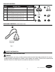
PACKAGE CONTENTS PART A B C D E F DESCRIPTION QUANTITY Light Kit Fitter Glass Shade Bulb Socket Ring (preassembled to light kit fitter (A)) Hex Nut (preassembled to light kit fitter (A)) Lock Washer (preassembled to light kit fitter (A)) 1 4 4 4 1 A B C D E F 1 HARDWARE CONTENTS (shown actual size) AA Pull Chain Extension Qty. 1 SAFETY INFORMATION READ AND SAVE THESE INSTRUCTIONS.
SAFETY INFORMATION DANGER • DO NOT connect this fixture to an electrical system that does not provide a means for equipment grounding. Never use a fixture in a two-wire system that is not grounded. Installing a fixture into an electrical system not having a proper grounding means could cause metal parts of the fixture to carry electrical currents if any of the fixture wires, wire connections or splices were to become broken, cut or loose during the mounting or normal operation of the fixture.
SAFETY INFORMATION CAUTION • To reduce the risk of fire or electric shock, this light kit fitter (A) should only be used with the compatible ceiling fan models (sold separately) listed below: BDB52AB5N, BDB52AB5P, BDB52ABZ5P, BDB52ABZC5N, BDB52ABZC5P, BDB52BB5P, BDB52BNK5N, BDB52BNK5P, BDB52BP5P, BDB52LW5N. PREPARATION Before beginning assembly of product, make sure all parts are present. Compare parts with package contents list and hardware contents list.
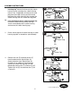
ASSEMBLY INSTRUCTIONS 2a. If the existing fan doesn’t have a switch housing cap, remove the three existing switch housing screws and lower the switch housing from the fan. If applicable, disconnect the male plug from the motor housing and the female plug from the switch housing, then remove the switch housing from the switch housing plate. 2b. If the existing fan has a switch housing cap, remove the three existing switch housing screws at the bottom of the switch housing and remove the switch housing cap.
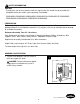
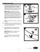
ASSEMBLY INSTRUCTIONS 5a. Remove wire connectors from WHITE and BLUE (or BLACK) wires labeled FOR LIGHT in switch housing/fan. Connect WHITE wire from light kit fitter (A) to WHITE wire from fan. Connect BLACK wire from light kit fitter (A) to BLUE (or BLACK) wire from fan. Use previously removed wire connectors to make the connections.
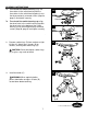
ASSEMBLY INSTRUCTIONS 7a. 7b. To re-install the switch housing, align the three holes in the switch housing with the three holes in the switch housing plate. Insert the three previously removed screws (Step 2a, page 5) and tighten securely. To re-install the switch housing cap, align the three holes in the switch housing cap with the three holes in the bottom of the switch housing. Insert the three previously removed screws (Step 2b, page 5) and tighten securely.
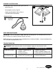
ASSEMBLY INSTRUCTIONS 10. Attach pull chain extension (AA) to pull chain on light kit fitter (A). 10 A Restore power and test light kit. If lights do not function, please refer to TROUBLESHOOTING below. Hardware Used AA Pull Chain Extension x 1 AA CARE AND MAINTENANCE IMPORTANT: Shut off main power supply. Wipe with soft damp cloth. Use window cleaner to clean glass. Do not use an abrasive cleaner on glass or fixture. Bulb Replacement: Use 60-watt max.
WARRANTY The distributor warrants all of its lighting fixtures against defects in materials and workmanship for one (1) year from the date of purchase. If within this period the product is found to be defective, take a copy of the bill of sale as a proof of purchase and the product in its original carton to the place of purchase. The distributor will, at its option, repair, replace or refund the purchase price to the consumer.